TEA1532
Philips Semiconductors
GreenChip II SMPS control IC
In fixed frequency continuous conduction mode, the internal oscillator determines the start
of the next converter stroke.
In both operating modes, a cycle skipping mode is activated at very low power (standby)
levels.
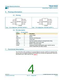
7.1 Start-up, mains enabling operation level and undervoltage lock out
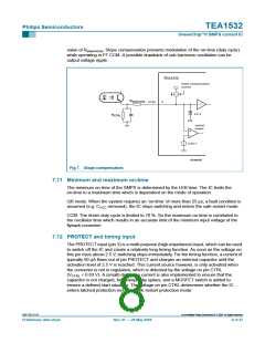
Refer to Figure 10 and Figure 11. Initially, the IC is self supplying from the rectified mains
voltage via pin DRAIN. Supply capacitor CVCC (at pin 1) is charged by the internal start-up
current source to a level of about 4 V or higher, depending on the drain voltage. Once the
drain voltage exceeds the Vm (mains-dependent operation-enabling level), the start-up
current source will continue charging capacitor CVCC (switch S1 will be opened); see
Figure 1. The IC will activate the power converter as soon as the voltage on pin VCC
passes the Vstart level. The IC supply is taken over by the auxiliary winding as soon as the
output voltage reaches its intended level and the IC supply from the mains voltage is
subsequently stopped for high efficiency operation (green function).
The moment the voltage on pin VCC drops below VUVLO (undervoltage lock out), the IC
stops switching and enters a safe restart from the rectified mains voltage. Inhibiting the
auxiliary supply by external means causes the converter to operate in a stable,
well-defined burst mode.
7.2 Supply management
All (internal) reference voltages are derived from a temperature compensated, on-chip
band gap circuit.
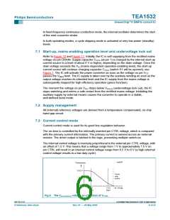
7.3 Current control mode
Current control mode is used for its good line regulation behavior.
The on-time is controlled by the internally inverted pin CTRL voltage, which is compared
with the primary current information. The primary current is sensed across an external
resistor. The driver output is latched in the logic, preventing multiple switch-on.
The internal control voltage is inversely proportional to the external pin CTRL voltage, with
an offset of 1.5 V. This means that a voltage range from 1 V to approximately 1.5 V on
pin CTRL will result in an internal control voltage range from 0.5 V to 0 V (a high external
control voltage results in a low duty cycle).
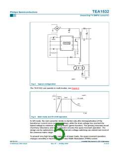
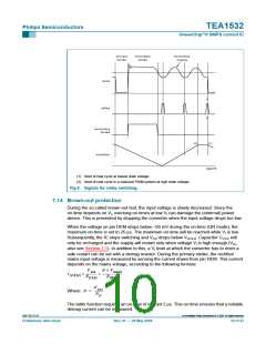
coa016
V
sense(max)
0.52 V
Cycle
skip
active
25 mV
1 V
(typ)
1.5 V
(typ)
V
CTRL
Fig 6. The Vsense(max) voltage as a function of VCTRL
Rev. 01 — 28 May 2004
.
9397 750 13113
© Koninklijke Philips Electronics N.V. 2004. All rights reserved.
Preliminary data sheet
6 of 27

 NXP [ NXP ]