TEA1532
Philips Semiconductors
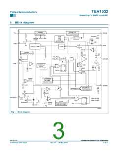
7.4 Oscillator
GreenChip II SMPS control IC
The fixed frequency of the oscillator is set by an internal current source and capacitor.
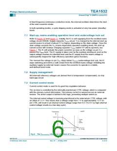
7.5 Cycle skipping
At very low power levels, a cycle skipping mode activates. An internal control voltage
(Vsense(max)) lower than 25 mV will inhibit switch-on of the external power MOSFET until
this voltage increases to a higher value; see Figure 6.
7.6 Demagnetization (QR operation)
The system will be in Discontinuous Conduction Mode (DCM) (QR operation) when
resistor RDEM is applied. The oscillator will not start a new primary stroke until the
secondary stroke has ended.
Demagnetization features a cycle-by-cycle output short-circuit protection which
immediately reduces the frequency (longer off-time), thereby reducing the power level.
Demagnetization recognition is suppressed during the first tsupp time. This suppression
may be necessary in applications where the transformer has a large leakage inductance
and at low output voltages or start-up.
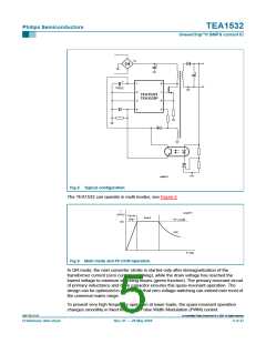
7.7 Continuous Conduction Mode (CCM)
It is also possible to operate the IC in the so-called Fixed Frequency Continuous
Conduction Mode (FF CCM). This mode is activated by connecting pin DEM to ground
and connecting pin DRAIN to the rectified constant Vi voltage; see Figure 13.
7.8 Overcurrent Protection (OCP)
The current in the transformer primary is measured accurately by the internal
cycle-by-cycle source current limit circuit using the external sense resistor Rsense
.
The accuracy of the current limit circuit allows the transformer core to have a minimum
specification for the output power required. The OCP circuit limits the ‘sense’ voltage to an
internal level, and is activated after the leading edge blanking period, tleb generated by the
Leading Edge Blanking (LEB) circuit.
7.9 Control pin protection
If pin CTRL becomes open-circuit or is disconnected, a fault condition is assumed and the
converter will stop operating immediately. Operation recommences when the fault
condition is removed.
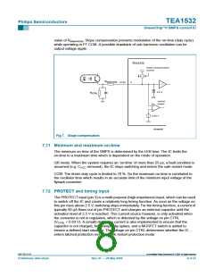
7.10 Adjustable slope compensation
A slope compensation function has been added at pin CTRL; see Figure 7. The slope
compensation function prevents sub-harmonic oscillation in CCM at duty cycles over
50 %. The CTRL voltage is modulated by sourcing a (non-constant) current out of
pin CTRL and adding a series resistor Rslopecomp. This increases the CTRL voltage
proportionally with the on-time, which therefore limits the OCP level. Thus, a longer
on-time results in a higher CTRL voltage, however, this increase in CTRL voltage will
actually decrease the on-time. Slope compensation can be adjusted by changing the
9397 750 13113
© Koninklijke Philips Electronics N.V. 2004. All rights reserved.
Preliminary data sheet
Rev. 01 — 28 May 2004
7 of 27

 NXP [ NXP ]