TEA1532
Philips Semiconductors
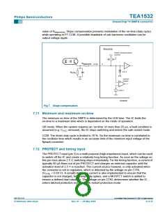
7.17 Driver
GreenChip II SMPS control IC
The driver circuit to the Gate of the power MOSFET has a current sourcing capability of
typically 170 mA and a current sink capability of typically 700 mA. This permits fast
turn-on and turn-off of the power MOSFET for efficient operation.
A low driver source current has been chosen to limit the ∆V/∆t at switch-on. This reduces
Electro Magnetic Interference (EMI) and also limits the current spikes across Rsense
.
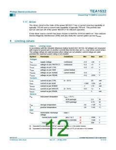
8. Limiting values
Table 3:
Limiting values
In accordance with the Absolute Maximum Rating System (IEC 60134). All voltages are measured
with respect to ground (pin 2); positive currents flow into the chip; pin VCC may not be current driven.
The voltage ratings are valid provided other ratings are not violated; current ratings are valid
provided the maximum power rating is not violated.
Symbol
Voltages
VCC
Parameter
Conditions
Min
Max
Unit
supply voltage
continuous
continuous
−0.4
−0.4
−0.4
-
+20
+5
+5
-
V
V
V
V
V
V
VPROTECT
VCTRL
voltage on pin PROTECT
voltage on pin CTRL
voltage on pin DEM
voltage on pin SENSE
voltage on pin DRAIN
VDEM
current limited
current limited
VSENSE
VDRAIN
Currents
ICTRL
−0.4
−0.4
-
+650
current on pin CTRL
current on pin DEM
current on pin SENSE
current on pin DRIVER
current on pin DRAIN
d < 10 %
d < 10 %
-
50
mA
µA
mA
A
IDEM
−1000
−1
+250
+10
+2
ISENSE
IDRIVER
IDRAIN
−0.8
-
5
mA
General
Ptot
total power dissipation
Tamb < 70 °C
SO8 package
DIP8 package
-
0.5
W
W
°C
°C
-
0.75
+150
+145
Tstg
Tj
storage temperature
junction temperature
−55
−20
ESD
VESD
electrostatic discharge
voltage
class 1
[1]
[1]
[2]
human body model
pins 1 to 7
-
-
-
2000
1500
200
V
V
V
pin 8 (DRAIN)
machine model
[1] Equivalent to discharging a 100 pF capacitor through a 1.5 kΩ series resistor.
[2] Equivalent to discharging a 200 pF capacitor through a 0.75 µH coil and a 10 Ω resistor.
9397 750 13113
© Koninklijke Philips Electronics N.V. 2004. All rights reserved.
Preliminary data sheet
Rev. 01 — 28 May 2004
12 of 27

 NXP [ NXP ]