TEA1532
Philips Semiconductors
GreenChip II SMPS control IC
9. Thermal characteristics
Table 4:
Symbol
Rth(j-a)
Thermal characteristics
Parameter
Conditions
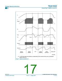
Typ
150
95
Unit
K/W
K/W
thermal resistance from
junction to ambient
in free air; SO8 package
in free air; DIP8 package
10. Characteristics
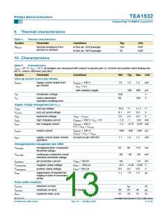
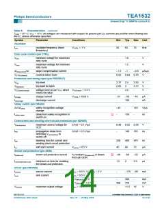
Table 5:
Characteristics
Tamb = 25 °C; VCC = 15 V; all voltages are measured with respect to ground (pin 2); currents are positive when flowing into
the IC; unless otherwise specified.
Symbol
Parameter
Conditions
Min
Typ
Max
Unit
Start-up current source (pin DRAIN)
IDRAIN
supply current drawn from
pin DRAIN
VDRAIN > 100 V;
VCC = 0 V
1.0
1.2
1.4
mA
with auxiliary supply
-
100
300
-
µA
V
VB
breakdown voltage
650
60
-
-
Vm
mains-dependent
100
V
operation-enabling level
Supply voltage management (pin VCC
)
Vstart
VUVLO
Vhys
start-up voltage
10.3
8.1
11
11.7
9.3
V
lock-out undervoltage
hysteresis voltage
8.7
2.3
−1
V
V
start − VUVLO
2.0
2.6
V
Ich(h)
Ich(l)
high charging current
low charging current
VDRAIN > 100 V; VCC < 3V
−1.2
−1.2
−0.8
mA
VDRAIN > 100 V;
−0.75 −0.45 mA
3 V < VCC < VUVLO
Irestart
Ioper
restart current
VDRAIN > 100 V;
−650 −550 −450 µA
VUVLO < VCC < Vstart
supply current under normal
operation
no load on pin DRIVER
1.1
1.3
1.5
mA
Demagnetization management (pin DEM)
Vth(DEM)
demagnetization comparator
threshold voltage
50
80
−50
-
110
−20
−10
mV
mV
Vth(CCM)
continuous conduction mode
detection threshold voltage
−80
Iprot(dem)
Vclamp(neg)
Vclamp(pos)
tsupp
pin protection current
negative clamp voltage
positive clamp voltage
VDEM = 50 mV
IDEM = −500 µA
IDEM = 250 µA
−60
−0.5
0.5
nA
V
−0.45 −0.40
0.7
1.5
0.9
1.9
V
suppression of transformer
ringing at start of secondary
stroke
1.1
µs
Pulse width modulator
ton(min)
ton(max)
δmax
minimum on-time
-
tleb
25
70
-
ns
µs
%
maximum on-time
QR mode
20
67
30
73
maximum duty-cycle
9397 750 13113
© Koninklijke Philips Electronics N.V. 2004. All rights reserved.
Preliminary data sheet
Rev. 01 — 28 May 2004
13 of 27

 NXP [ NXP ]