Philips Semiconductors
Preliminary specification
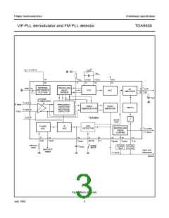
VIF-PLL demodulator and FM-PLL detector
TDA9800
CHARACTERISTICS
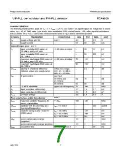
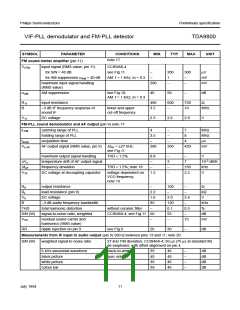
The following characteristics apply for VP = 5 V; Tamb = +25 °C; see Table 1 for input frequencies and picture to sound
ratios; VilF = 10 mV RMS value (sync level); video modulation DSB; residual carrier: 10%; video signal in accordance
with CCIR line 17 or NTC-7 Composite; measurements taken in Fig.3 unless otherwise specified
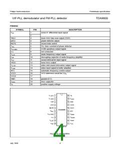
SYMBOL
PARAMETER
supply voltage (pin 20)
supply current
CONDITIONS
note 1
MIN.
4.5
TYP.
MAX.
8.8
UNIT
VP
IP
5
V
51
60
69
mA
Vision IF input (pins 1 and 2)
Vi
input sensitivity (RMS value) at
38.9 MHz and 45.75 MHz
−1 dB video at output
−
50
90
100
−
µV
µV
mV
mV
dB
input sensitivity (RMS value) at
58.75 MHz
−
60
maximum input signal (RMS value) at +1 dB video at output
38.9 MHz and 45.75 MHz
70
80
−
150
160
0.7
maximum input signal (RMS value) at
58.75 MHz
−
∆Vo int.
internal IF amplitude difference
between picture and sound carrier
within AGC range;
B/G: ∆f = 5.5 MHz;
M/N: ∆f = 4.5 MHz
1
GIF
IF gain control
see Fig.4
38.9 MHz and
45.75 MHz
64
62
70
−
dB
58.75 MHz
68
−
dB
MHz
kΩ
pF
V
B
−3 dB IF bandwidth
upper cut-off frequency 70
100
2.2
1.7
3.4
−
Ri
input resistance (differential)
input capacitance (differential)
DC input voltage
1.7
2.7
2.5
3.8
Ci
1.2
V1, 2
3.0
note 2
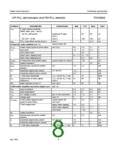
True synchronous video demodulator
fVCO
maximum oscillator frequency for
carrier regeneration
f = 2fPC
125
130
−
MHz
∆fVCO
Vo ref
oscillator drift (free running) as a
function of temperature
IAFC = 0; note 3
fPC = 38.9 MHz
−
−
±20
ppm/K
oscillator swing at pins 16 and 17
(RMS value)
−
120
100
80
−
−
−
−
mV
mV
mV
MHz
f
f
PC = 45.75 MHz
PC = 58.75 MHz
−
−
∆fPC
vision carrier capture range
(negative)
1.5
2
vision carrier capture range (positive)
acquisition time
1.5
2
−
MHz
ms
tacqu
BL = 60 kHz; note 4
−
−
30
July 1994
7

 NXP [ NXP ]