Philips Semiconductors
Preliminary specification
VIF-PLL demodulator and FM-PLL detector
TDA9800
with 90 degree phase difference independent of
frequency.
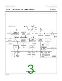
FUNCTIONAL DESCRIPTION
Vision IF input
Video amplifier, buffer and noise clipping
The vision IF amplifier consists of three AC-coupled
differential amplifier stages; each stage comprises a
controlled feedback network by means of emitter
degeneration.
The video amplifier is a wide bandwidth operational
amplifier with internal feedback. A nominal positive
modulated video signal of 1 V (p-p) is present on the
composite video output (pin 13). The input impedance of
the 7 dB wideband buffer amplifier (with internal feedback)
is suitable for ceramic sound trap filters. The CVBS output
(pin 7) provides a positive video signal of 2 V (p-p). Noise
clipping is provided internally.
IF and tuner AGC
The automatic control voltage to maintain the video output
signal at a constant level is generated according to the
transmission standard. Since the TDA9800 is suitable for
negative modulation only the peak-sync level is detected.
The AGC detector charges and discharges the capacitor
on pin 19 to set the IF gain and the tuner gain. The AGC
capacitor voltage is transferred to an internal IF control
signal, and is fed to the tuner AGC to generate the tuner
AGC output current on pin 12 (open-collector output). The
tuner AGC voltage take over point is adjusted on pin 3.
This allows the tuner and the IF SAW filter to be matched
to achieve the optimum IF input level.
Sound demodulation
The FM sound intercarrier signal is fed to pin 11 and
through a limiter amplifier before it is demodulated. This
achieves high sensitivity and high AM suppression. The
limiter amplifier consists of seven internal AC-coupled
stages, minimizing the DC offset.
The FM-PLL demodulator consists of an RC-oscillator,
loop filter and phase detector. The oscillator frequency is
locked on the FM intercarrier signal from the limiter
amplifier. As a result of this locking, the RC-oscillator is
frequency-modulated.
Frequency detector, phase detector and video
demodulator
The modulating signal voltage (AF signal) is used to
control the oscillator frequency. By this, the FM-PLL
operates as an FM demodulator.
The audio frequency amplifier with internal feedback is
designed for high gain and high common mode rejection.
The low-level AF signal output from the FM-PLL
demodulator is amplified and buffered in a low-ohmic
audio signal output stage (pin 9). An external decoupling
capacitor on pin 10 removes the DC voltage from the audio
amplifier input.
The IF amplifier output signal is fed to a frequency detector
and to a phase detector. During acquisition the frequency
detector produces a DC current which is proportional to the
frequency difference between the input and the VCO
signal. After frequency lock-in the phase detector
produces a DC current proportional to the phase
difference between the VCO and the input signal. Via the
loop filter the DC current of either frequency detector or
phase detector is converted into a DC voltage, which
controls the VCO frequency.
By using the sound mute switch (pin 5) the AF amplifier is
set to mute state.
The video demodulator is a linear multiplier, designed for
low distortion and wide bandwidth. The vision IF input
signal is multiplied by the in-phase component of the VCO
output. The demodulated output signal is fed via an
integrated low-pass filter (fg = 12 MHz) to the video
amplifier for suppression of the carrier harmonics.
VCO and travelling wave divider
The VCO operates with a symmetrically-connected
reference LC-circuit, operating at double vision carrier
frequency. Frequency control is performed by an internal
varicap diode. The voltage to set the VCO frequency to the
actual frequency of double vision carrier frequency, is also
amplified and converted for the AFC output current.
The VCO signal is divided-by-two in a travelling wave
divider, which generates two differential output signals
July 1994
5

 NXP [ NXP ]