TDA8931
Philips Semiconductors
Power comparator 1 × 20 W
14.2 Output current limiting
The output current is limited by the OCP with a threshold level of 3.3 A (minimum). During
normal operation the output current should not exceed this threshold level, otherwise the
output signal is distorted. The peak output current should stay below 3.3 A and can be
estimated using the following equation:
VP
IO
≤
≤ 3.3
(4)
------------------------------------------------------------------------------
2 × (RDSon + RL + Rcoil + RESR
)
Where:
IO = output current in the load in
VP = supply voltage (VDDP − VSSP
)
RDSon = on-resistance power switch
RL = load impedance
Rcoil = series resistance output coil
RESR = ESR of the single-ended capacitor
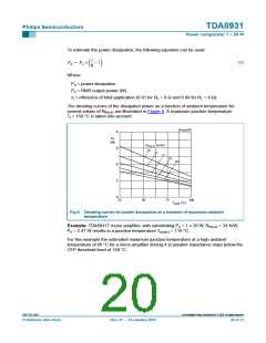
Example: With a 4 Ω load the OCP will be triggered below a supply voltage of 28 V. This
will result in an absolute maximum output power of Po = 26 W at THD = 10 %.
14.3 Low pass filter considerations
For a flat frequency response (second order Butterworth filter) it is necessary to change
the LC-filter components (L1 and C14) according to the speaker impedance. Table 12
shows the required components values in case of a 4 W, 6 W or 8 W speaker impedance.
Table 12: Filter components values
Speaker impedance
(Ω)
L1 value
(µH)
C14 value
(nF)
4
6
8
22
33
47
680
470
330
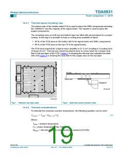
14.4 Thermal behavior (printed-circuit board considerations)
The SO20 package of the TDA8931T has special thermal corner leads, significantly
increasing the power capability (reducing Rth). The corner leads (pins 1, 10, 11 and 20)
should be attached to a copper area (VSS) on the PCB for cooling.
The typical thermal resistance Rth(j-a) of the TDA8931T is 24 K/W (free air and natural
convection) when soldered on a double sided FR4 PCB with 35 µm copper layer and
cooling area of approximately of 28 cm2.
9397 750 13847
© Koninklijke Philips Electronics N.V. 2005. All rights reserved.
Preliminary data sheet
Rev. 01 — 14 January 2004
18 of 31

 NXP [ NXP ]