TDA8931
Philips Semiconductors
Power comparator 1 × 20 W
14.1 Output power estimation
The output power, just before clipping, can be estimated using the following equation:
2
RL
× V
----------------------------------------------------------------
P
RL + RDSon + Rcoil + RESR
-------------------------------------------------------------------------------------
8 × RL
Po(1%)
=
(2)
Where:
P
o(1%) = output power just before clipping at THD = 1 %
RL = load impedance
RDSon = on-resistance power switch
Rcoil = series resistance output coil
RESR = ESR of the single-ended capacitor
VP = supply voltage (VDDP − VSSP
)
Example: Substituting RL = 4 Ω, RDSon = 0.22 Ω (at Tj = 25 °C), Rcoil = 0.045 Ω,
RESR = 0.06 Ω and VP = 22 V results in output power Po = 12.9 W.
The output power at THD = 10 % can be estimated by:
Po(10%) = 1.25 × Po(1%)
(3)
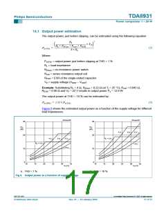
Figure 6 shows the estimated output power as a function of the supply voltage for different
load impedances.
001aac236
001aac237
30
30
P
P
O
O
(W)
(W)
6 Ω
4 Ω
8 Ω
20
20
4 Ω
6 Ω
8 Ω
R
L
= 3 Ω
R
L
= 3 Ω
10 Ω
10 Ω
10
10
0
0
10
15
20
25
30
35
10
15
20
25
30
35
V
(V)
V (V)
P
P
a. THD = 1 %.
b. THD = 10 %.
Fig 6. Output power as a function of supply voltage
9397 750 13847
© Koninklijke Philips Electronics N.V. 2005. All rights reserved.
Preliminary data sheet
Rev. 01 — 14 January 2004
17 of 31

 NXP [ NXP ]