Philips Semiconductors
Preliminary specification
26 W BTL and 2 × 13 W SE or
4 × 13 W SE power amplifier
TDA8512J
CONTENTS
15
PACKAGE OUTLINE
16
SOLDERING
1
2
3
4
5
6
7
8
FEATURES
16.1
Introduction to soldering through-hole mount
packages
Soldering by dipping or by solder wave
Manual soldering
Suitability of through-hole mount IC packages
for dipping and wave soldering methods
APPLICATIONS
GENERAL DESCRIPTION
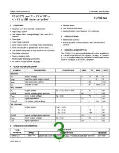
QUICK REFERENCE DATA
ORDERING INFORMATION
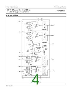
BLOCK DIAGRAM
16.2
16.3
16.4
17
18
19
DATA SHEET STATUS
DEFINITIONS
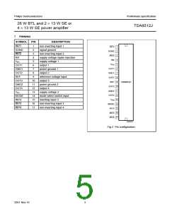
PINNING
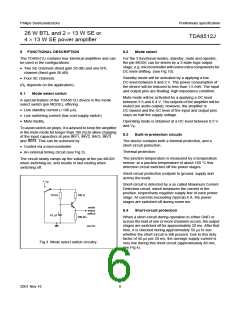
FUNCTIONAL DESCRIPTION
DISCLAIMERS
8.1
8.2
8.3
8.4
Mode select switch
Mode select
Built-in protection circuits
Short-circuit protection
9
LIMITING VALUES
10
11
12
13
14
HANDLING
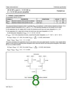
THERMAL CHARACTERISTICS
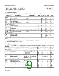
DC CHARACTERISTICS
AC CHARACTERISTICS
APPLICATION INFORMATION
14.1
14.2
14.3
14.4
14.5
14.6
14.7
Input configuration
Output power
Power dissipation
Supply Voltage Ripple Rejection (SVRR)
Switch-on and switch-off
PCB layout and grounding
Typical performance characteristics
2001 Nov 16
2

 NXP [ NXP ]