Philips Semiconductors
Objective specification
Integrated PAL and PAL/NTSC TV
processors
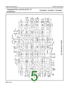
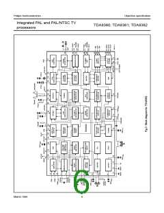
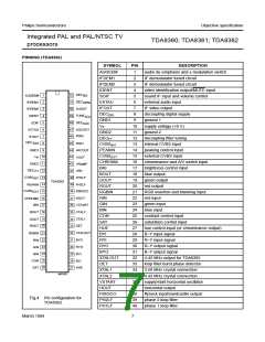
TDA8360; TDA8361; TDA8362
The oscillator network is internal.
Because of the spread of internal
When the pin is left open-circuit the
trap is switched off so that the circuit
can also be used for S-VHS
applications.
Sound circuit
The sound bandpass and trap filters
have to be connected externally. The
filtered intercarrier signal is fed to a
limiter circuit and is demodulated by
means of a PLL demodulator. The
PLL circuit tunes itself automatically
to the incoming signal, consequently,
no adjustment is required.
components an automatic adjustment
circuit has been added to the IC.
The circuit compares the oscillator
frequency with that of the crystal
oscillator in the colour decoder. This
results in a free-running frequency
which deviates less than 2% from the
typical value.
The luminance delay line and the
delay for the peaking circuit are also
realised by means of gyrator circuits.
Colour decoder
The volume is DC controlled. The
composite audio output signal has an
amplitude of 700 mV RMS at a
volume control setting of −6 dB. The
de-emphasis capacitor has to be
connected externally. The
non-controlled audio signal can be
obtained from this pin via a buffer
stage. The amplitude of this signal is
350 mV RMS.
The colour decoder in the various ICs
contains an alignment-free crystal
oscillator, a colour killer circuit and
colour difference demodulators.
The 90° phase shift for the reference
signal is achieved internally. Because
the main differences of the 3 ICs are
found in the colour decoder the
The circuit employs a second control
loop to generate the drive pulses for
the horizontal driver stage.
X-ray protection can be realised by
switching the pin of the second
control loop to the positive supply line.
The detection circuit must be
connected externally. When the X-ray
protection is active the horizontal
output voltage is switched to a high
level. When the voltage on this pin
returns to its normal level the
various types will be discussed.
TDA8360
The TDA8361 and TDA8362 external
audio input signal must have an
amplitude of 350 mV RMS. The
audio/video switch is controlled via
the chrominance input pin.
This IC contains only a PAL decoder.
Depending on the frequency of the
crystals which are connected to the IC
the decoder can demodulate all PAL
standards. Because the horizontal
oscillator is calibrated by using the
crystal frequency as a reference the
4.4 MHz crystal must be connected to
pin 35 and the 3.5 MHz crystal to
pin 34. When only one crystal is
connected to the IC the other crystal
pin must be connected to the positive
supply rail via a 47 kΩ resistor. For
applications with two 3.5 MHz
crystals both must be connected to
pin 34 and the switching between the
crystals must be made externally.
Switching of the crystals is only
allowed directly after the vertical
retrace. The circuit will indicate
whether a PAL signal has been
identified by the colour decoder via
the saturation control pin.
horizontal output is released again.
The IC contains a start-up circuit for
the horizontal oscillator. When this
feature is required a current of 6.5 mA
has to be supplied to pin 36. For an
application without start-up both
supply pins (10 and 36) must be
connected to the 8 V supply line.
Synchronization circuit
The sync separator is preceded by a
voltage controlled amplifier which
adjusts the sync pulse amplitude to a
fixed level. The sync pulses are then
fed to the slicing stage (separator)
which operates at 50% of the
amplitude.
The drive signal for the vertical ramp
generator is generated by means of a
divider circuit. The RC network for the
ramp generator is external.
The separated sync pulses are fed to
the first phase detector and to the
coincidence detector. The
coincidence detector is used for
transmitter identification and to detect
whether the line oscillator is
synchronized. When the circuit is not
synchronized the voltage on the
peaking control pin (pin 14) is LOW
so that this condition can be detected
externally. The first PLL has a very
high static steepness, this ensures
that the phase of the picture is
independent of the line frequency.
The line oscillator operates at twice
the line frequency.
Integrated video filters
The circuit contains a chrominance
bandpass and trap circuit. The filters
are realised by means of gyrator
circuits and are automatically tuned
by comparing the tuning frequency
with the crystal frequency of the
decoder.
In the TDA8361 and TDA8362 the
chrominance trap is active only when
the separate chrominance input pin is
connected to ground or to the positive
supply voltage and when a colour
signal is recognized.
When two crystals are connected to
the IC the output voltage of the video
identification circuit indicates the
frequency of the incoming
chrominance signal.
March 1994
9

 NXP [ NXP ]