Philips Semiconductors
Product specification
Brushless DC motor drive circuit
TDA5144
A timing function is incorporated into the device for internal
timing and for timing of the reverse rotation detection.
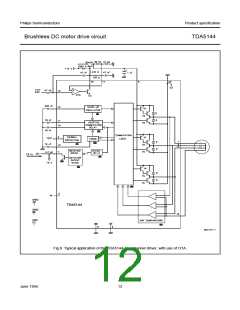
Introduction (see Fig.8)
Full-wave driving of a three phase motor requires three
push-pull output stages. In each of the six possible states
two outputs are active, one sourcing (H) and one sinking
(L). The third output presents a high impedance (Z) to the
motor, which enables measurement of the motor
back-EMF in the corresponding motor coil by the EMF
comparator at each output. The commutation logic is
responsible for control of the output transistors and
selection of the correct EMF comparator. In Table 1 the
sequence of the six possible states of the outputs has
been depicted.
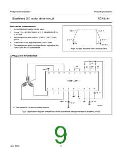
The TDA5144 also contains an uncommitted
transconductance amplifier (OTA) that can be used as a
control amplifier. The output is capable of directly driving
an external power transistor.
The TDA5144 is designed for systems with low current
consumption: use of I2L logic, adaptive base drive for the
output transistors (patented).
Adjustments
The system has been designed in such a way that the
tolerances of the application components are not critical.
However, the approximate values of the following
components must still be determined:
Table 1 Output states.
STATE
MOT1(1)
MOT2(1)
MOT3(1)
1
2
3
4
5
6
Z
H
H
Z
L
L
L
H
Z
L
• The start capacitor; this determines the frequency of the
start oscillator.
Z
H
H
Z
• The two capacitors in the adaptive commutation delay
circuit; these are important in determining the optimum
moment for commutation, depending on the type and
loading of the motor.
L
Z
H
L
• The timing capacitor; this provides the system with its
timing signals.
Note
1. H = HIGH state;
L = LOW state;
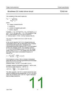
THE START CAPACITOR (CAP-ST)
Z = high-impedance OFF-state.
This capacitor determines the frequency of the start
oscillator. It is charged and discharged, with a current of
2 µA, from 0.05 to 2.2 V and back to 0.05 V. The time
taken to complete one cycle is given by:
The zero-crossing in the motor EMF (detected by the
comparator selected by the commutation logic) is used to
calculate the correct moment for the next commutation,
that is, the change to the next output state. The delay is
calculated (depending on the motor loading) by the
adaptive commutation delay block.
tstart = (2.15 × C) s (with C in µF)
The start oscillator is reset by a commutation pulse and so
is only active when the system is in the start-up mode. A
pulse from the start oscillator will cause the outputs to
change to the next state (torque in the motor). If the
movement of the motor generates enough EMF the
TDA5144 will run the motor. If the amount of EMF
generated is insufficient, then the motor will move one step
only and will oscillate in its new position. The amplitude of
the oscillation must decrease sufficiently before the arrival
of the next start pulse, to prevent the pulse arriving during
the wrong phase of the oscillation.
Because of high inductive loading the output stages
contain flyback diodes. The output stages are also
protected by a current limiting circuit and by thermal
protection of the six output transistors.
The detected zero-crossings are used to provide speed
information. The information has been made available on
the FG output pin. This is an open collector output and
provides an output signal with a frequency that is half the
commutation frequency.
The system will only function when the EMF voltage from
the motor is present. Therefore, a start oscillator is
provided that will generate commutation pulses when no
zero-crossings in the motor voltage are available.
June 1994
10

 NXP [ NXP ]