Philips Semiconductors
Product specification
Brushless DC motor drive circuit
TDA5144
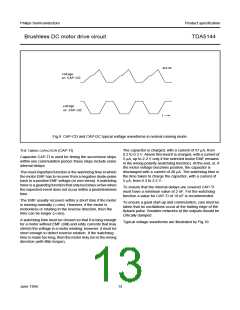
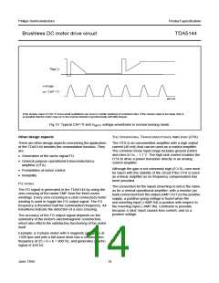
If the chosen value of CAP-TI is too small oscillations can occur in certain positions of a blocked rotor. If the chosen value is too large, then it
is possible that the motor may run in the reverse direction (synchronously with little torque).
Fig.10 Typical CAP-TI and VMOT1 voltage waveforms in normal running mode.
Other design aspects
THE OPERATIONAL TRANSCONDUCTANCE AMPLIFIER (OTA)
There are other design aspects concerning the application
of the TDA5144 besides the commutation function. They
are:
The OTA is an uncommitted amplifier with a high output
current (40 mA) that can be used as a control amplifier.
The common mode input range includes ground (GND)
and rises to VP − 1.7 V. The high sink current enables the
OTA to drive a power transistor directly in an analog
control amplifier.
• Generation of the tacho signal FG
• General purpose operational transconductance
amplifier (OTA)
Although the gain is not extremely high (0.3 S), care must
be taken with the stability of the circuit if the OTA is used
as a linear amplifier as no frequency compensation has
been provided.
• Possibilities of motor control
• Reliability.
FG SIGNAL
The convention for the inputs (inverting or not) is the same
as for a normal operational amplifier: with a resistor (as
load) connected from the output (AMP OUT) to the positive
supply, a positive-going voltage is found when the
non-inverting input (+AMP IN) is positive with respect to
the inverting input (−AMP IN). Confusion is possible
because a ‘plus’ input causes less current, and so a
positive voltage.
The FG signal is generated in the TDA5144 by using the
zero-crossing of the motor EMF from the three motor
windings. Every zero-crossing in a (star connected) motor
winding is used to toggle the FG output signal. The FG
frequency is therefore half the commutation frequency. All
transitions indicate the detection of a zero-crossing.
The accuracy of the FG output signal depends on the
symmetry of the motor's electromagnetic construction,
which also effects the satisfactory functioning of the motor
itself.
Example: a 3-phase motor with 6 magnetic pole-pairs at
1500 rpm and with a full-wave drive has a commutation
frequency of 25 × 6 × 6 = 900 Hz, and generates a tacho
signal of 450 Hz.
June 1994
14

 NXP [ NXP ]