Philips Semiconductors
Product specification
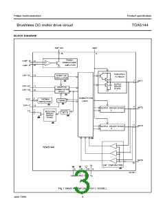
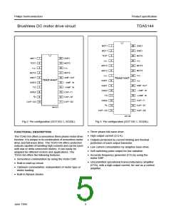
Brushless DC motor drive circuit
TDA5144
LIMITING VALUES
In accordance with the Absolute Maximum Rating System (IEC 134).
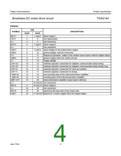
SYMBOL
VP
PARAMETER
supply voltage
CONDITIONS
MIN.
MAX.
UNIT
−
18
V
V
VI
input voltage; all pins except
VMOT
VI < 18 V
−0.3
VP + 0.5
VVMOT
VO
VMOT input voltage
output voltage
−0.5
17
V
AMP OUT and FG
GND
−1
VP
V
V
V
MOT0, MOT1, MOT2 and MOT3
VVMOT + VDHF
VI
input voltage CAP-ST, CAP-TI,
CAP-CD and CAP-DC
−
2.5
Tstg
Tamb
Ptot
storage temperature
−55
0
+150
+70
−
°C
°C
W
V
operating ambient temperature
total power dissipation
electrostatic handling
see Figs 4 and 5
−
Ves
see Chapter “Handling”
−
500
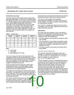
MBD536
MBD557
3
2
3
P
P
tot
tot
(W)
(W)
2
1.62
1.38
1
1
0
0
50
0
50
100
150
200
50
0
50
100
150
200
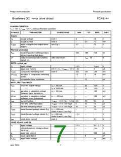
70
o
o
T
( C)
T
( C)
amb
amb
Fig.4 Power derating curve (SOT163-1; SO20L).
Fig.5 Power derating curve (SOT136-1; SO28L).
HANDLING
Every pin withstands the ESD test according to “MIL-STD-883C class 2”. Method 3015 (HBM 1500 Ω, 100 pF) 3 pulses +
and 3 pulses − on each pin referenced to ground.
June 1994
6

 NXP [ NXP ]