Philips Semiconductors
Product specification
Brushless DC motor drive circuit
TDA5144
The oscillation of the motor is given by:
1
fosc
=
----------------------------------
Kt × I × p
2π ----------------------
J
where:
Kt = torque constant (N.m/A)
I = current (A)
p = number of magnetic pole-pairs
J = inertia J (kg.m2)
Example: J = 72 × 10−6 kg.m2, K = 25 × 10−3 N.m/A, p = 6
and I = 0.5 A; this gives fosc = 5 Hz. If the damping is high
then a start frequency of 2 Hz can be chosen or
t = 500 ms, thus C = 0.5/2 = 0.25 µF (choose 220 nF).
THE ADAPTIVE COMMUTATION DELAY (CAP-CD AND
CAP-DC)
In this circuit capacitor CAP-CD is charged during one
commutation period, with an interruption of the charging
current during the diode pulse. During the next
commutation period this capacitor (CAP-CD) is discharged
at twice the charging current. The charging current is
8.1 µA and the discharging current 16.2 µA; the voltage
range is from 0.9 to 2.2 V. The voltage must stay within
this range at the lowest commutation frequency of
interest, fC1
:
8.1 × 10⁻⁶
-------------------------
f × 1.3
6231
------------
fC1
C =
=
(C in nF)
If the frequency is lower, then a constant commutation
delay after the zero-crossing is generated by the discharge
from 2.2 to 0.9 V at 16.2 µA;
maximum delay = (0.076 × C) ms (with C in nF).
Example: nominal commutation frequency = 900 Hz and
the lowest usable frequency = 400 Hz; so:
6231
CAP-CD =
= 15.6 (choose 18 nF)
------------
400
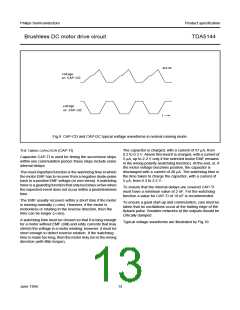
The other capacitor, CAP-DC, is used to repeat the same
delay by charging and discharging with 15.5 µA. The same
value can be chosen as for CAP-CD. Figure 9 illustrates
typical voltage waveforms.
June 1994
11

 NXP [ NXP ]