Philips Semiconductors
Product specification
I2C-bus autosync deflection controller for
PC monitors
TDA4856
APPLICATION INFORMATION
V
CC
handbook, full pagewidth
V
i
2
V
V
(1)
V
HDRV
HPLL2
R6
6
L
3
BDRV
D2
SOFT START
OTA
S
R
Q
Q
2.5 V
TR1
INVERTING
BUFFER
HORIZONTAL
OUTPUT
STAGE
DISCHARGE
5
3
4
D1
C1
1
horizontal
flyback pulse
V
V
BIN
BOP
R5
4
R1
R3
V
BSENS
R4
C4
R2
MGM080
C2
C
BOP
>10 nF
EWDRV
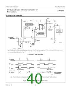
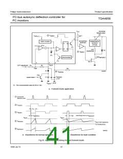
For f < 50 kHz and C2 < 47 nF calculation formulas and behaviour of the OTA are the same as for an OP. An exception is the limited output current at
BOP (pin 3). See Chapter “Characteristics”, Row Head “B+ control section; see Figs 22 and 23”.
(1) The recommended value for R6 is 1 kΩ.
a. Feedback mode application.
handbook, full pagewidth
1
horizontal
flyback pulse
2
3
V
HDRV
t
on
t
V
BDRV
t
d(BDRV)
off(min)
V
= V
BSENS
V
BOP
V
4
RESTART(BSENS)
BSENS
V
STOP(BSENS)
MBG600
b. Waveforms for normal operation.
c. Waveforms for fault condition.
Fig.22 Application and timing for feedback mode.
1999 Jul 13
40

 NXP [ NXP ]