Philips Semiconductors
Product specification
Enhanced octal universal asynchronous
receiver/transmitter (Octal UART)
SCC2698B
The selected set of rates is available for use by the receiver and
transmitter.
OPCR – Output Port Configuration Register
OPCR[7] – MPP Function Select
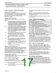
ACR[6:4] – Counter/Timer Mode and Clock Source Select
This field selects the operating mode of the counter/timer and its
clock source (see Table 4).
When this bit is a zero, the MPP pins function as inputs, to be used
as general purpose inputs or as receiver or transmitter external
clock inputs. When this bit is set, the MPP pins function as outputs.
MPP1 will be a TxRDY indicator, and MPP2 will be an
RxRDY/FFULL indicator.
The MPI1 pin available as the Counter/Timer clock source is MPI1
a,c,e, and g only.
OPCR[6:4] – MPOb Output Select
This field programs the MPOb output pin to provide one of the
following:
Table 4. ACR[6:4] Operating Mode
[6:4]
Mode
Clock Source
000
Request-to-send active-Low output (RTSN). This output
is asserted and negated via the command register. Mode
RTSN can be programmed to be automatically reset after
the character in the transmitter is completely shifted out
or when the receiver FIFO and receiver shift register are
full using MR2[5] and MR1[7], respectively.
0 0 0 Counter MPI1a pin
0 0 1 Counter MPI1a pin divided by 16
0 1 0 Counter TxC–1XA clock of the transmitter
0 1 1 Counter Crystal or MPI pin (X1/CLK) divided by 16
001
The counter/timer output. In the timer mode, this output is
a square wave with a period of twice the value (in clock
periods) of the contents of the CTPU and CTPL. In the
counter mode, the output remains high until the terminal
count is reached, at which time it goes low. The output
returns to the High state when the counter is stopped by
a stop counter command.
1 0 0 Timer
1 0 1 Timer
1 1 0 Timer
1 1 1 Timer
MPI1a pin
MPI1a pin divided by 16
Crystal or external clock (X1/CLK)
Crystal or MPI pin (X1/CLK) divided by 16
010
011
100
The 1X clock for the transmitter, which is the clock that
shifts the transmitted data. If data is not being
transmitted, a non-synchronized 1X clock is output.
NOTE: The timer mode generates a squarewave.
ACR[3:0] – MPI1b, MPI0b, MPI1a, MPI0a Change-of-State
Interrupt Enable
The 16X clock for the transmitter. This is the clock
selected by CSR[3:0], and is a 1X clock if CSR[3:0] =
1111.
This field selects which bits of the input port change register (IPCR)
cause the input change bit in the interrupt status register, ISR[7], to
be set. If a bit is in the ‘on’ state, the setting of the corresponding bit
in the IPCR will also result in the setting of ISR[7], which results in
the generation of an interrupt output if IMR[7] = 1. If a bit is in the
‘off’ state, the setting of that bit in the IPCR has no effect on ISR[7].
The 1X clock for the receiver, which is the clock that
samples the received data. If data is not being received,
a non-synchronized 1X clock is output.
101
110
111
The 16X clock for the receiver. This is the clock selected
by CSR[7:4], and is a 1X clock if CSR[7:4] = 1111.
The transmitter register ready signal, which is the same
as SR[2].
IPCR – Input Port Change Register
IPCR[7:4] – MPI1b, MPI0b, MPI1a, MPI0a Change-of-State
These bits are set when a change of state, as defined in the Input
Port section of this data sheet, occurs at the respective pins. They
are cleared when the IPCR is read by the CPU. A read of the IPCR
also clears ISR[7], the input change bit in the interrupt status
register. The setting of these bits can be programmed to generate
an interrupt to the CPU.
The receiver ready or FIFO full signal.
OPCR[3] – Power Down Mode Select
This bit, when set, selects the power-down mode. In this mode, the
2698B oscillator is stopped and all functions requiring this clock are
suspended. The contents of all registers are saved. It is
recommended that the transmitter and receiver be disabled prior to
placing the 2698B in this mode. This bit is reset with RESET
asserted. Note that this bit must be set to a logic 1 after power up.
Only OPCR[3] in block A controls the power-down mode.
IPCR[3:0] – MPI1b, MPI0b, MPI1a, MPI0a Change-of-State
These bits provide the current state of the respective inputs. The
information is unlatched and reflects the state of the inputs pins
during the time the IPCR is read.
OPCR[2:0] – MPOa Output Select
This field programs the MPOa output pin to provide one of the same
functions as described in OPCR[6:4].
ISR – Interrupt Status Register
This register provides the status of all potential interrupt sources.
The contents of this register are masked by the interrupt mask
register (IMR). If a bit in the ISR is a ‘1’ and the corresponding bit in
the IMR is also a ‘1’, the INTRN output is asserted (Low). If the
corresponding bit in the IMR is a zero, the state of the bit in the ISR
has no effect on the INTRN output. Note that the IMR does not mask
the reading of the ISR; the true status is provided regardless of the
contents of the IMR.
ACR – Auxiliary Control Register
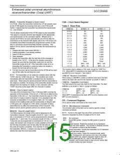
ACR[7] – Baud Rate Generator Set Select
This bit selects one of two sets of baud rates generated by the BRG.
Set 1: 50, 110, 134.5, 200, 300, 600, 1.05k, 1.2k, 2.4k, 4.8k, 7.2k,
9.6k, and 38.4k baud.
Set 2: 75, 110, 150, 300, 600, 1.2k, 1.8k, 2.0k, 2.4k, 4.8k, 9.6k,
19.2k, and 38.4k baud.
17
2000 Jan 31

 NXP [ NXP ]