Philips Semiconductors
Product specification
Radio tuning PLL frequency synthesizer
SAA1057
OPERATION DESCRIPTION
Control information
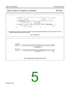
The following functions can be controlled with the data word bits in latch B. For data word format and bit position see
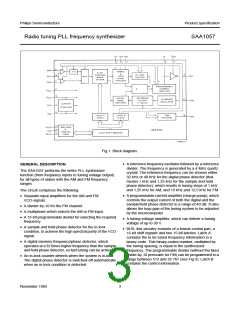
Fig.3.
FM
FM/AM selection; ‘1’ = FM, ‘0’ = AM
REFH
CP3
CP2
CP1
CP0
SB2
reference frequency selection; ‘1’ = 1,25 kHz, ‘0’ = 1 kHz (sample and hold phase detector)
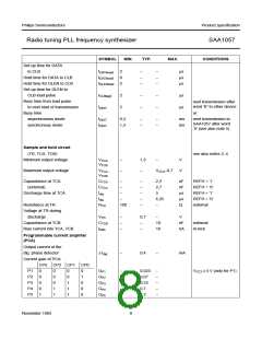
control bits for the programmable current amplifier (see section Characteristics)
enables last 8 bits (SLA to T0) of data word B; ‘1’ = enables, ‘0’ = disables; when programmed ‘0’, the
last 8 bits of data word B will be set to ‘0’ automatically
SLA
load mode of latch A; ‘1’ = synchronous, ‘0’ = asynchronous
PDM1
PDM0
phase detector mode
PDM1
PDM0
digital phase detector
0
1
1
X
0
1
automatic on/off
on
off
BRM
bus receiver mode bit; in this mode the supply current of the BUS receiver will be switched-off
automatically after a data transmission (current-draw is reduced); ‘1’ = current switched; ‘0’ = current
always on
T3
T2
T1
T0
test bit; must be programmed always ‘0’
test bit; selects the reference frequency (32 or 40 kHz) to the TEST pin
test bit; must be programmed always ‘0’
test bit; selects the output of the programmable counter to the TEST pin
T3
0
T2
0
T1
0
T0
0
TEST (pin 18)
1
0
1
0
0
reference frequency
0
0
0
1
output programmable
counter
0
1
0
1
output in-lock counter
‘0’ = out-lock
‘1’ = in-lock
November 1983
4

 NXP [ NXP ]