PDIUSBD12
USB interface device with parallel bus
Philips Semiconductors
It should be noted that the tolerance of the internal resistors is higher (25%) than that
specified by the USB specification (5%). However, the overall VSE voltage
specification for the connection can still be met with good margin. The decision to
make sure of this feature lies with the users.
6.7 GoodLink
Good USB connection indication is provided through GoodLink technology. During
enumeration, the LED indicator will blink ON momentarily corresponding to the
enumeration traffic. When the PDIUSBD12 is successfully enumerated and
configured, the LED indicator will be permanently ON. Subsequent successful (with
acknowledgement) transfer to and from the PDIUSBD12 will blink OFF the LED.
During suspend, the LED will be OFF.
This feature provides a user-friendly indicator on the status of the USB device, the
connected hub and the USB traffic. It is a useful field diagnostics tool to isolate faulty
equipment. This feature helps lower field support and hotline costs.
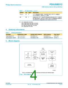
6.8 Memory Management Unit (MMU) and Integrated RAM
The MMU and the integrated RAM buffer the difference in speed between USB,
running in bursts of 12 Mbits/s and the parallel interface to the microcontroller. This
allows the microcontroller to read and write USB packets at its own speed.
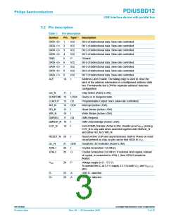
6.9 Parallel and DMA Interface
A generic parallel interface is defined for ease-of-use, speed, and allows direct
interfacing to major microcontrollers. To a microcontroller, the PDIUSBD12 appears
as a memory device with 8-bit data bus and 1 address bit (occupying 2 locations).
The PDIUSBD12 supports both multiplexed and non-multiplexed address and data
bus. The PDIUSBD12 also supports DMA (Direct Memory Access) transfer which
allows the main endpoint (endpoint 2) to directly transfer to and from the local shared
memory. Both single-cycle and burst mode DMA transfers are supported.
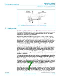
6.10 Example of parallel interface to an 80C51 microcontroller
In the example shown in Figure 3, the ALE pin is permanently tied LOW to signify a
separate address and data bus configuration. The A0 pin of the PDIUSBD12
connects to any of the 80C51 I/O ports. This port controls the command or data
phase to the PDIUSBD12. The multiplexed address and data bus of the 80C51 can
now be connected directly to the data bus of the PDIUSBD12. The address phase will
be ignored by the PDIUSBD12. The clock input signal of the 80C51 (pin XTAL1) can
be provided by output CLKOUT of the PDIUSBD12.
9397 750 09238
© Koninklijke Philips Electronics N.V. 2001. All rights reserved.
Product data
Rev. 08 — 20 December 2001
6 of 35

 NXP [ NXP ]