PDIUSBD12
USB interface device with parallel bus
Philips Semiconductors
15. Dynamic characteristics
Table 16: AC characteristics (AI/O pins; FULL speed)[1]
CL = 50 pF; RPU = 1.5 kΩ on D+ to VCC; unless otherwise specified.
Symbol Parameter
Conditions
Min
Max Unit
Driver characteristics
tR
rise time
10% to 90%
10% to 90%
4
20
ns
ns
%
V
tF
fall time
4
20
tRFM
VCRS
rise/fall time matching (tR/tF)
output signal crossover voltage
90
1.3
110
2.0
Driver timings
tEOPT source EOP width
tDEOP differential data to EOP transition skew
Receiver timings:
tJR1 receiver data jitter tolerance to next transition
tJR2 receiver data jitter tolerance for paired transitions
see Figure 16
see Figure 16
160
175
+5
ns
ns
−2
−18.5 +18.5 ns
−9
+9
-
ns
ns
[2]
[2]
tEOPR1 EOP width at receiver
must reject as EOP;
see Figure 16
40
tEOPR2 EOP width at receiver
must accept as EOP;
see Figure 16
82
−
ns
[1] Test circuit, see Figure 22.
[2] Characterized but not implemented as production test. Guaranteed by design.
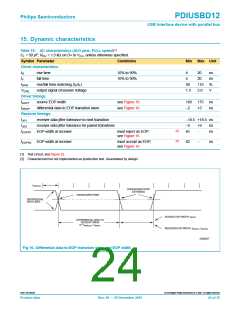
t
PERIOD
CROSSOVER POINT
EXTENDED
CROSSOVER POINT
DIFFERENTIAL
DATA LINES
SOURCE EOP WIDTH: t
EOPT
DIFFERENTIAL DATA TO
SEO/EOP SKEW
N * t
+ t
DEOP
PERIOD
RECEIVER EOP WIDTH: t
, t
EOPR1 EOPR2
SV00837
Fig 16. Differential data-to-EOP transition skew and EOP width.
9397 750 09238
© Koninklijke Philips Electronics N.V. 2001. All rights reserved.
Product data
Rev. 08 — 20 December 2001
24 of 35

 NXP [ NXP ]