PDIUSBD12
USB interface device with parallel bus
Philips Semiconductors
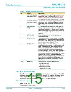
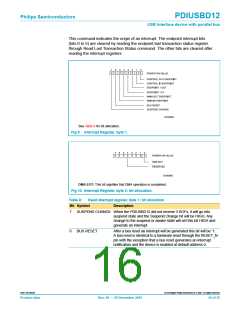
This command indicates the origin of an interrupt. The endpoint interrupt bits
(bits 0 to 5) are cleared by reading the endpoint last transaction status register
through Read Last Transaction Status command. The other bits are cleared after
reading the interrupt registers.
See Table 8 for bit allocation.
Fig 9. Interrupt Register, byte 1.
DMA EOT: This bit signifies that DMA operation is completed.
Fig 10. Interrupt Register, byte 2: bit allocation.
Table 8:
Read interrupt register, byte 1: bit allocation
Description
Bit Symbol
7
6
SUSPEND CHANGE When the PDIUSBD12 did not receive 3 SOFs, it will go into
suspend state and the Suspend Change bit will be HIGH. Any
change to the suspend or awake state will set this bit HIGH and
generate an interrupt.
BUS RESET
After a bus reset an interrupt will be generated this bit will be ‘1’.
A bus reset is identical to a hardware reset through the RESET_N
pin with the exception that a bus reset generates an interrupt
notification and the device is enabled at default address 0.
9397 750 09238
© Koninklijke Philips Electronics N.V. 2001. All rights reserved.
Product data
Rev. 08 — 20 December 2001
16 of 35

 NXP [ NXP ]