PDIUSBD12
USB interface device with parallel bus
Philips Semiconductors
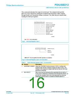
Table 5:
Set mode command, Configuration byte: bit allocation
Bit
Symbol
Description
7 to 6
ENDPOINT
CONFIGURAT
ION
These two bits set the endpoint configurations as follows:
mode 0 (Non-ISO mode)
mode 1 (ISO-OUT mode)
mode 2 (ISO-IN mode)
mode 3 (ISO-I/O mode)
See Section 8 “Endpoint description” for more details.
4
SoftConnect
A ‘1’ indicates that the upstream pull-up resistor will be connected
if VBUS is available. A ‘0’ means that the upstream resistor will not
be connected. The programmed value will not be changed by a
bus reset.
3
2
INTERRUPT
MODE
A ‘1’ indicates that all errors and “NAKing” are reported and will
generate an interrupt. A ‘0’ indicates that only OK is reported. The
programmed value will not be changed by a bus reset.
CLOCK
RUNNING
A ‘1’ indicates that the internal clocks and PLL are always running
even during Suspend state. A ‘0’ indicates that the internal clock,
crystal oscillator and PLL are stopped whenever not needed. To
meet the strict Suspend current requirement, this bit needs to be
set to ‘0’. The programmed value will not be changed by a bus
reset.
1
NO
A ‘1’ indicates that CLKOUT will not switch to LazyClock. A ‘0’
LAZYCLOCK indicates that the CLKOUT switches to LazyClock 1ms after the
Suspend pin goes HIGH. LazyClock frequency is 30 kHz ± 40%.
The programmed value will not be changed by a bus reset.
7
0
6
0
5
X
4
X
3
1
2
0
1
1
0
1
POWER ON VALUE
CLOCK DIVISION FACTOR
RESERVED
SET_TO_ONE
SOF-ONLY INTERRUPT MODE
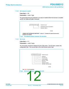
SV00862
See Table 6 for bit allocation.
Fig 7. Set mode command, Clock division factor byte.
9397 750 09238
© Koninklijke Philips Electronics N.V. 2001. All rights reserved.
Product data
Rev. 08 — 20 December 2001
13 of 35

 NXP [ NXP ]