PCA9557
NXP Semiconductors
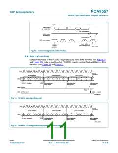
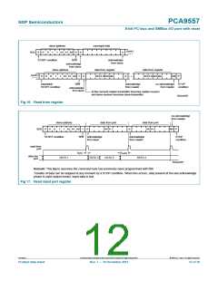
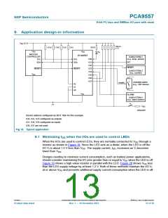
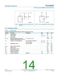
8-bit I2C-bus and SMBus I/O port with reset
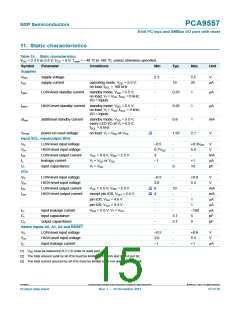
11. Static characteristics
Table 10. Static characteristics
VDD = 2.3 V to 5.5 V; VSS = 0 V; Tamb = 40 C to +85 C; unless otherwise specified.
Symbol
Parameter
Conditions
Min
Typ
Max
Unit
Supplies
VDD
supply voltage
supply current
2.3
-
-
5.5
25
V
IDD
operating mode; VDD = 5.5 V;
no load; fSCL = 100 kHz
19
A
IstbL
LOW-level standby current
standby mode; VDD = 5.5 V;
no load; VI = VSS; fSCL = 0 kHz;
I/O = inputs
-
-
-
-
0.25
0.25
0.8
1
A
A
mA
V
IstbH
Istb
VPOR
HIGH-level standby current standby mode; VDD = 5.5 V;
no load; VI = VDD; fSCL = 0 kHz;
I/O = inputs
1
additional standby current
standby mode; VDD = 5.5 V;
every LED I/O at VI = 4.3 V;
fSCL = 0 kHz
1
[1]
power-on reset voltage
no load; VI = VDD or VSS
1.65
2.1
Input SCL; input/output SDA
VIL
VIH
IOL
IL
LOW-level input voltage
HIGH-level input voltage
LOW-level output current
leakage current
0.5
-
+0.3VDD
V
0.7VDD
-
5.5
-
V
VOL = 0.4 V; VDD = 2.3 V
VI = VDD or VSS
VI = VSS
3
-
mA
A
pF
1
-
-
+1
10
Ci
input capacitance
6
I/Os
VIL
VIH
IOL
IOH
LOW-level input voltage
HIGH-level input voltage
LOW-level output current
HIGH-level output current
0.5
-
+0.8
V
2.0
-
5.5
V
[2]
[3]
VOL = 5.5 V; VDD = 2.3 V
except pin IO0; VOH = 2.4 V
pin IO0; VOH = 4.6 V
8
4
-
10
-
-
mA
mA
A
A
A
pF
pF
-
-
1
pin IO0; VOH = 3.3 V
-
-
1
ILI
Ci
input leakage current
input capacitance
output capacitance
VDD = 5.5 V; VI = VSS
-
-
100
-
3.7
3.7
5
5
Co
-
Select inputs A0, A1, A2 and RESET
VIL
VIH
ILI
LOW-level input voltage
HIGH-level input voltage
input leakage current
0.5
2.0
1
-
-
-
+0.8
5.5
+1
V
V
A
[1] VDD must be lowered to 0.2 V in order to reset part.
[2] The total amount sunk by all I/Os must be limited to 100 mA and 25 mA per bit.
[3] The total current sourced by all I/Os must be limited to 85 mA and 20 mA per bit.
PCA9557
All information provided in this document is subject to legal disclaimers.
© NXP B.V. 2013. All rights reserved.
Product data sheet
Rev. 7 — 10 December 2013
15 of 30

 NXP [ NXP ]