Philips Semiconductors
Preliminary specification
80C51 8-bit microcontroller
8K/256 OTP, 8 channel 10 bit A/D, I2C, PWM,
capture/compare, high I/O, low voltage (2.7V–5.5V), low power
P87C552
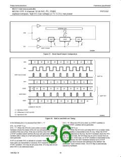
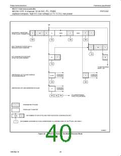
INTERNAL BUS
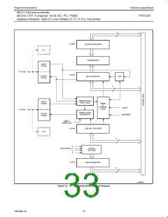
SDA
8
BSD7
S1DAT
ACK
SCL
SHIFT PULSES
SU00969
Figure 37. Serial Input/Output Configuration
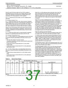
SDA
SCL
D7
D6
D5
D4
D3
D2
D1
D0
A
SHIFT ACK & S1DAT
SHIFT IN
ACK
(2)
(2)
(2)
(2)
(2)
(2)
(2)
(2)
(2)
(2)
(2)
(2)
(2)
(2)
(2)
A
S1DAT
(1)
(2)
(1)
SHIFT BSD7
SHIFT OUT
BSD7
D7
D6
D5
D4
D3
D2
D1
D0
(3)
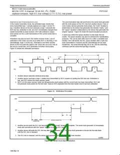
LOADED BY THE CPU
(1) Valid data in S1DAT
(2) Shifting data in S1DAT and ACK
(3) High level on SDA
SU00970
Figure 38. Shift-in and Shift-out Timing
In the following text, it is assumed that ENS1 = “1”.
STA = “0”: When the STA bit is reset, no START condition or
repeated START condition will be generated.
STA, THE START FLAG
STA = “1”: When the STA bit is set to enter a master mode, the SIO1
hardware checks the status of the I2C bus and generates a START
condition if the bus is free. If the bus is not free, then SIO1 waits for
a STOP condition (which will free the bus) and generates a START
condition after a delay of a half clock period of the internal serial
clock generator.
STO, THE STOP FLAG
STO = “1”: When the STO bit is set while SIO1 is in a master mode,
a STOP condition is transmitted to the I C bus. When the STOP
2
condition is detected on the bus, the SIO1 hardware clears the STO
flag. In a slave mode, the STO flag may be set to recover from an
error condition. In this case, no STOP condition is transmitted to the
2
I C bus. However, the SIO1 hardware behaves as if a STOP
If STA is set while SIO1 is already in a master mode and one or
more bytes are transmitted or received, SIO1 transmits a repeated
START condition. STA may be set at any time. STA may also be set
when SIO1 is an addressed slave.
condition has been received and switches to the defined “not
addressed” slave receiver mode. The STO flag is automatically
cleared by hardware.
36
1999 Mar 30

 NXP [ NXP ]