Philips Semiconductors
Preliminary specification
80C51 8-bit microcontroller
8K/256 OTP, 8 channel 10 bit A/D, I2C, PWM,
capture/compare, high I/O, low voltage (2.7V–5.5V), low power
P87C552
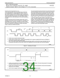
If the STA and STO bits are both set, the a STOP condition is
transmitted to the I C bus if SIO1 is in a master mode (in a slave
mode, SIO1 generates an internal STOP condition which is not
transmitted). SIO1 then transmits a START condition.
When SIO1 is in the addressed slave transmitter mode, state C8H
will be entered after the last serial is transmitted (see Figure 42).
When SI is cleared, SIO1 leaves state C8H, enters the not
addressed slave receiver mode, and the SDA line remains at a high
level. In state C8H, the AA flag can be set again for future address
recognition.
2
STO = “0”: When the STO bit is reset, no STOP condition will be
generated.
When SIO1 is in the not addressed slave mode, its own slave
address and the general call address are ignored. Consequently, no
acknowledge is returned, and a serial interrupt is not requested.
SI, THE SERIAL INTERRUPT FLAG
SI = “1”: When the SI flag is set, then, if the EA and ES1 (interrupt
enable register) bits are also set, a serial interrupt is requested. SI is
set by hardware when one of 25 of the 26 possible SIO1 states is
entered. The only state that does not cause SI to be set is state
F8H, which indicates that no relevant state information is available.
2
Thus, SIO1 can be temporarily released from the I C bus while the
bus status is monitored. While SIO1 is released from the bus,
START and STOP conditions are detected, and serial data is shifted
in. Address recognition can be resumed at any time by setting the
AA flag. If the AA flag is set when the part’s own slave address or
the general call address has been partly received, the address will
be recognized at the end of the byte transmission.
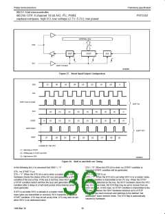
While SI is set, the low period of the serial clock on the SCL line is
stretched, and the serial transfer is suspended. A high level on the
SCL line is unaffected by the serial interrupt flag. SI must be reset
by software.
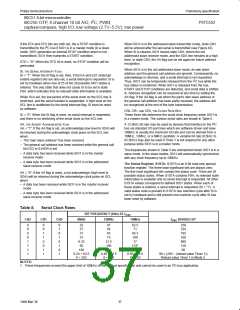
CR0, CR1, AND CR2, THE CLOCK RATE BITS
SI = “0”: When the SI flag is reset, no serial interrupt is requested,
and there is no stretching of the serial clock on the SCL line.
These three bits determine the serial clock frequency when SIO1 is
in a master mode. The various serial rates are shown in Table 5.
2
AA, THE ASSERT ACKNOWLEDGE FLAG
A 12.5kHz bit rate may be used by devices that interface to the I C
AA = “1”: If the AA flag is set, an acknowledge (low level to SDA) will
be returned during the acknowledge clock pulse on the SCL line
when:
bus via standard I/O port lines which are software driven and slow.
100kHz is usually the maximum bit rate and can be derived from a
16MHz, 12MHz, or a 6MHz oscillator. A variable bit rate (0.5kHz to
62.5kHz) may also be used if Timer 1 is not required for any other
purpose while SIO1 is in a master mode.
– The “own slave address” has been received
– The general call address has been received while the general call
bit (GC) in S1ADR is set
The frequencies shown in Table 5 are unimportant when SIO1 is in a
slave mode. In the slave modes, SIO1 will automatically synchronize
with any clock frequency up to 100kHz.
– A data byte has been received while SIO1 is in the master
receiver mode
– A data byte has been received while SIO1 is in the addressed
slave receiver mode
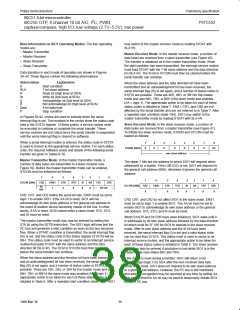
The Status Register, S1STA: S1STA is an 8-bit read-only special
function register. The three least significant bits are always zero.
The five most significant bits contain the status code. There are 26
possible status codes. When S1STA contains F8H, no relevant state
information is available and no serial interrupt is requested. All other
S1STA values correspond to defined SIO1 states. When each of
these states is entered, a serial interrupt is requested (SI = “1”). A
valid status code is present in S1STA one machine cycle after SI is
set by hardware and is still present one machine cycle after SI has
been reset by software.
AA = “0”: if the AA flag is reset, a not acknowledge (high level to
SDA) will be returned during the acknowledge clock pulse on SCL
when:
– A data has been received while SIO1 is in the master receiver
mode
– A data byte has been received while SIO1 is in the addressed
slave receiver mode
Table 5.
Serial Clock Rates
BIT FREQUENCY (kHz) AT f
OSC
CR2
CR1
CR0
6MHz
12MHz
16MHz
f
DIVIDED BY
OSC
0
0
0
0
1
1
1
1
0
0
1
1
0
0
1
1
0
1
0
1
0
1
0
1
23
27
31
37
6.25
50
47
54
63
62.5
71
83.3
100
17
256
224
192
160
960
120
60
75
12.5
100
200
1
133
1
100
0.24 < 62.5
0 < 255
267
0.49 < 62.5
0 < 254
0.65 < 55.6
0 < 253
96 × (256 – (reload value Timer 1))
Reload value Timer 1 in Mode 2.
NOTES:
2
2
1. These frequencies exceed the upper limit of 100kHz of the I C-bus specification and cannot be used in an I C-bus application.
37
1999 Mar 30

 NXP [ NXP ]