Philips Semiconductors
Preliminary specification
80C51 8-bit microcontroller
8K/256 OTP, 8 channel 10 bit A/D, I2C, PWM,
capture/compare, high I/O, low voltage (2.7V–5.5V), low power
P87C552
More Information on SIO1 Operating Modes: The four operating
modes are:
may switch to the master receiver mode by loading S1DAT with
SLA+R).
– Master Transmitter
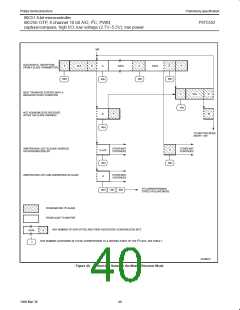
Master Receiver Mode: In the master receiver mode, a number of
data bytes are received from a slave transmitter (see Figure 40).
The transfer is initialized as in the master transmitter mode. When
the start condition has been transmitted, the interrupt service routine
must load S1DAT with the 7-bit slave address and the data direction
bit (SLA+R). The SI bit in S1CON must then be cleared before the
serial transfer can continue.
– Master Receiver
– Slave Receiver
– Slave Transmitter
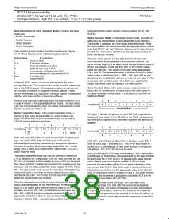
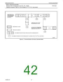
Data transfers in each mode of operation are shown in Figures
39–42. These figures contain the following abbreviations:
Abbreviation
S
SLA
R
W
A
A
Data
P
Explanation
Start condition
7-bit slave address
Read bit (high level at SDA)
Write bit (low level at SDA)
Acknowledge bit (low level at SDA)
Not acknowledge bit (high level at SDA)
8-bit data byte
When the slave address and the data direction bit have been
transmitted and an acknowledgment bit has been received, the
serial interrupt flag (SI) is set again, and a number of status codes in
S1STA are possible. These are 40H, 48H, or 38H for the master
mode and also 68H, 78H, or B0H if the slave mode was enabled
(AA = logic 1). The appropriate action to be taken for each of these
status codes is detailed in Table 7. ENS1, CR1, and CR0 are not
affected by the serial transfer and are not referred to in Table 7. After
a repeated start condition (state 10H), SIO1 may switch to the
master transmitter mode by loading S1DAT with SLA+W.
Stop condition
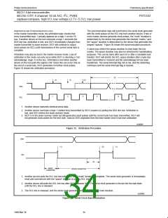
In Figures 39-42, circles are used to indicate when the serial
interrupt flag is set. The numbers in the circles show the status code
held in the S1STA register. At these points, a service routine must
be executed to continue or complete the serial transfer. These
service routines are not critical since the serial transfer is suspended
until the serial interrupt flag is cleared by software.
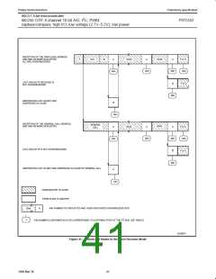
Slave Receiver Mode: In the slave receiver mode, a number of
data bytes are received from a master transmitter (see Figure 41).
To initiate the slave receiver mode, S1ADR and S1CON must be
loaded as follows:
When a serial interrupt routine is entered, the status code in S1STA
is used to branch to the appropriate service routine. For each status
code, the required software action and details of the following serial
transfer are given in Tables 6-10.
7
6
5
4
3
2
1
0
S1ADR (DBH)
X
X
X
X
X
X
X
GC
own slave address
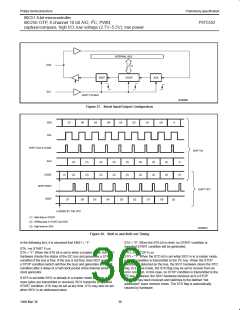
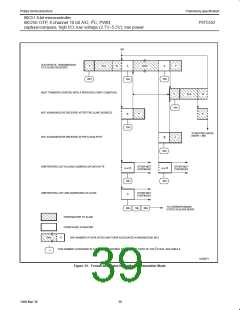
Master Transmitter Mode: In the master transmitter mode, a
number of data bytes are transmitted to a slave receiver (see
Figure 39). Before the master transmitter mode can be entered,
S1CON must be initialized as follows:
The upper 7 bits are the address to which SIO1 will respond when
addressed by a master. If the LSB (GC) is set, SIO1 will respond to
the general call address (00H); otherwise it ignores the general call
address.
7
6
5
4
3
2
1
0
7
6
5
4
3
2
1
0
S1CON (D8H)
CR2
ENS1
STA
STO
SI
AA
CR1
CR0
S1CON (D8H) CR2
ENS1
STA
STO
SI
AA
CR1
CR0
bit
rate
bit rate
1
0
0
0
X
X
1
0
0
0
1
X
X
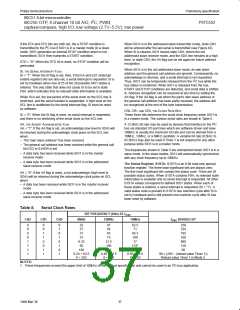
CR0, CR1, and CR2 define the serial bit rate. ENS1 must be set to
logic 1 to enable SIO1. If the AA bit is reset, SIO1 will not
acknowledge its own slave address or the general call address in
the event of another device becoming master of the bus. In other
words, if AA is reset, SIO0 cannot enter a slave mode. STA, STO,
and SI must be reset.
CR0, CR1, and CR2 do not affect SIO1 in the slave mode. ENS1
must be set to logic 1 to enable SIO1. The AA bit must be set to
enable SIO1 to acknowledge its own slave address or the general
call address. STA, STO, and SI must be reset.
When S1ADR and S1CON have been initialized, SIO1 waits until it
is addressed by its own slave address followed by the data direction
bit which must be “0” (W) for SIO1 to operate in the slave receiver
mode. After its own slave address and the W bit have been
received, the serial interrupt flag (I) is set and a valid status code
can be read from S1STA. This status code is used to vector to an
interrupt service routine, and the appropriate action to be taken for
each of these status codes is detailed in Table 8. The slave receiver
mode may also be entered if arbitration is lost while SIO1 is in the
master mode (see status 68H and 78H).
The master transmitter mode may now be entered by setting the
STA bit using the SETB instruction. The SIO1 logic will now test the
2
I C bus and generate a start condition as soon as the bus becomes
free. When a START condition is transmitted, the serial interrupt flag
(SI) is set, and the status code in the status register (S1STA) will be
08H. This status code must be used to vector to an interrupt service
routine that loads S1DAT with the slave address and the data
direction bit (SLA+W). The SI bit in S1CON must then be reset
before the serial transfer can continue.
When the slave address and the direction bit have been transmitted
and an acknowledgment bit has been received, the serial interrupt
flag (SI) is set again, and a number of status codes in S1STA are
possible. There are 18H, 20H, or 38H for the master mode and also
68H, 78H, or B0H if the slave mode was enabled (AA = logic 1). The
appropriate action to be taken for each of these status codes is
detailed in Table 6. After a repeated start condition (state 10H). SIO1
If the AA bit is reset during a transfer, SIO1 will return a not
acknowledge (logic 1) to SDA after the next received data byte.
While AA is reset, SIO1 does not respond to its own slave address
2
or a general call address. However, the I C bus is still monitored
and address recognition may be resumed at any time by setting AA.
This means that the AA bit may be used to temporarily isolate SIO1
2
from the I C bus.
38
1999 Mar 30

 NXP [ NXP ]