Philips Semiconductors
Product specification
Temperature monitor for microprocessor systems
NE1617
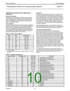
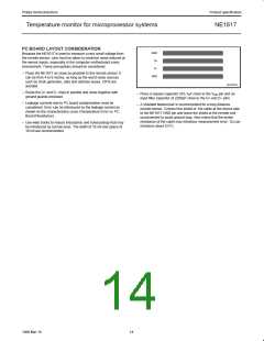
PC BOARD LAYOUT CONSIDERATION
Because the NE1617 is used to measure a very small voltage from
GND
the remote sensor, care must be taken to minimize noise induced at
the sensor inputs, especially in the computer motherboard noisy
D+
environment. These precautions should be considered:
D–
– Place the NE1617 as close as possible to the remote sensor. It
can be from 4 to 8 inches, as long as the worst noise sources
GND
such as clock generator, data and address buses, CRTs are
avoided.
SL01218
– Route the D+ and D– lines in parallel and close together with
ground guards enclosed.
– Place a bypass capacitor of 0.1µF close to the V pin and an
input filter capacitor of 2200pF close to the D+ and D– pins.
DD
– Leakage currents due to PC board contamination must be
considered. Error can be introduced by the leakage current as
shown on the characteristics curve (Temperature Error vs. PC
Board Resistance).
– A shielded twisted pair is recommended for a long distance
remote sensor. Connect the shield of the cable at the device side
to the NE1617 GND pin and leave the shield at the remote end
unconnected to avoid ground loop. Also notice that the series
resistance of the cable may introduce measurement error; 1Ω can
introduce about 0.5°C.
– Use wide tracks to reduce inductance and noise pickup that may
be introduced by narrow ones. The width of 10 mil and space of
10 mil are recommended.
14
1999 Mar 19

 NXP [ NXP ]