Philips Semiconductors
Product specification
Temperature monitor for microprocessor systems
NE1617
Power-up default condition
Upon power-up reset (power is switched off-on), the NE1617 goes
into this default condition:
SMBus interface
The device can communicate over a standard 2-wire serial interface
System Management Bus (SMBus) using the device pins SCLK and
SDATA. The device employs four standard SMBus protocols: Write
Byte, Read Byte, Send Byte and Receive Byte. Data formats of
those protocols are shown in Table 8 with following notifications:
– Interrupt latch is cleared, the ALERT output is pulled high by the
external pull-up resistor.
– The auto-conversion rate is at 0.25Hz; conversion rate data is
02H.
– The SMBus master initiates data transfer by establishing a start
condition (S) and terminates data transfer by generating a stop
condition (P).
– Temperature limits for both channels are +127°C for high limit, and
–55°C for low limit.
– Data is sent over the serial bus in sequence of 9 clock pulses
according to each 8-bit data byte followed by 1-bit status of the
device acknowledgement.
– Command pointer register is set to 00 for quickly reading the RIT.
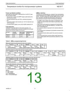
Fault detection
The NE1617 has a fault detector to the diode connection. The
connection is checked when a conversion is initiated and the proper
flags are set if the fault condition has occurred.
– The 7-bit slave address is equivalent to the selected address of
the device.
– The command byte is equivalent to the selected command of the
device register
D+ & D–
ALERT
OUTPUT
RET DATA
STORAGE
STATUS SET
FLAG
– The send byte format is often used for the one-shot conversion
command.
Opened
Shorted
Low
Low
127°C
127°C
B2 & B4
B4
– The receive byte format is used for quicker transfer data from a
device reading register which was previously selected by a read
byte format.
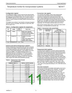
Table 8. SMBus programming format
Write byte format (for writing data byte to the device register):
ADDRESS WR ACK COMMAND
7 bits 1 bit = 0 by 8 bits
S
ACK
by
DATA
8 bits
ACK
by
P
device address device device register device
to register
device
Read byte format (for reading data byte from the device register):
ADDRESS WR ACK COMMAND ACK
7 bits 1 bit = 0 by 8 bits by
S
S
ADDRESS
7 bits
RD
ACK
DATA
8 bits
NACK
by
P
1 bit = 1 by
device address device device register device
device address
device
from
controller
register
Send byte format (for sending command without data, such as one–shot command):
S
ADDRESS
WR
ACK
COMMAND
ACK
P
7 bits
device address
1 bit = 0 by
8 bits
by
device
device register device
Receive byte format (for continuously reading from device register):
ADDRESS RD ACK DATA NACK
7 bits 1 bit = 1 by 8 bits by
S
P
device address device from register controller
NOTES:
S = Start condition
P = Stop condition
ACK = Acknowledged
NACK = Not acknowledged
13
1999 Mar 19

 NXP [ NXP ]