Philips Semiconductors
Product specification
Temperature monitor for microprocessor systems
NE1617
TEMPERATURE MONITOR WITH SMB SERIAL
INTERFACE
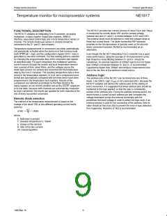
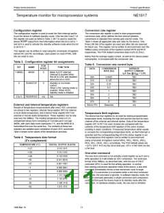
Registers
The device contains more than 9 registers. They are used to store
the data of device setup and operation results. Depending on the
bus communication (either read or write operations), each register
may be called by different names because each register may have
different sub-addresses or commands for read and write operations.
For example, the configuration register is called as WC for write
mode and as RC for read mode. Table 2 (Register Assignments)
shows the names, commands and functions of all registers as well
the register POR states.
Serial bus interface
The device can be connected to a standard 2-wire serial interface
System Management Bus (SMBus) as a slave device under the
control of a master device, using two device terminals SCLK and
SDATA. The operation of the device to the bus is described with
details in the following sections.
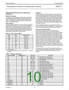
Slave address
The device address is defined by the logical connections applied to
the device pins ADD0 and ADD1. A list of selectable addresses are
shown in Table 1. The device address can be set to any one of
those nine combinations and more than one device can reside on
the same bus without address confliction. Note that the state of the
device address pins is sampled and latched not only at power-up
step but also at starting point of every conversion.
Note that attempting to write to a read-command or read from a
write-command will produce an invalid result. The reserved registers
are used for factory test purposes and should not be written to.
Low power standby modes
Upon POR, the device is reset to its normal free-running
auto-conversion operation mode. The device can be put into
standby mode by either using hardware control (connect the STBY
pin to LOW for hardware standby mode) or using software control
(set bit 6 of the configuration register to HIGH for software standby
mode). When the device is put in either one of the standby modes,
the supply current is reduced to less than 10µA if there is no SMBus
activity, all data in the device registers are retained and the SMBus
interface is still alive to bus communication. However, there is a
difference in the device ADC conversion operation between
hardware standby and software standby modes. In hardware
standby mode, the device conversion is inhibited and the one-shot
command does not initiate a conversion. In software standby mode,
the one-shot command will initiate a conversion for both internal and
external channels.
Table 1. Device slave address
ADD0*
GND
GND
GND
NC
ADD1*
GND
NC
ADDRESS BYTE
0011 000
0011 001
0011 010
0101 001
0101 010
0101 011
1001 100
V
DD
GND
NC
NC
NC
V
DD
V
DD
V
DD
V
DD
GND
NC
1001 101
1001 110
If a hardware standby command is received when the device is in
normal mode and a conversion is in progress, the conversion cycle
will stop and data in reading temperature registers will not be
updated.
V
DD
NC = Not Connected.
*
Any pull-up/down resistor used to connect to GND or V should
DD
be ≤ 2kΩ.
Table 2. Register assignments
REGISTER NAME
RIT
COMMAND BYTE
POR STATE
0000 0000
0000 0000
n/a
FUNCTION
Read internal or local temp byte
Read external or remote temp byte
Read status byte
00h
01h
02h
03h
04h
05h
06h
07h
08h
09h
0Ah
0Bh
0Ch
0Dh
0Eh
0Fh
10h
11h
12h
13h
RET
RS
RC
0000 0000
0000 0010
0111 1111
1100 1001
0111 1111
1100 1001
n/a
Read configuration byte
RCR
Read conversion rate byte
Read internal temp HIGH limit byte
Read internal tem low limit byte
Read external temp HIGH limit byte
Read external temp LOW limit byte
Write configuration byte
RIHL
RILL
REHL
RELL
WC
WCR
n/a
Write conversion rate byte
Write internal temp HIGH limit byte
Write internal temp LOW limit byte
Write external temp HIGH limit byte
Write external temp LOW limit byte
One shot command
WIHL
n/a
WILL
n/a
WEHL
WELL
n/a
n/a
OSHT
n/a
RESERVED
RESERVED
RESERVED
RESERVED
n/a
Reserved
n/a
Reserved
n/a
Reserved
n/a
Reserved
10
1999 Mar 19

 NXP [ NXP ]