Philips Semiconductors
Product specification
Temperature monitor for microprocessor systems
NE1617
Status register
Alert interrupt
The ALERT output is used to signal Alert interruption from the
device to the SMBus and is active low. Because this output is an
The content of the status register reflects condition status resulting
from all of these activities: comparisons between temperature
measurements and temperature limits, the status of ADC
conversion, and the hardware condition of the connection of external
diode to the device. Bit assignments and bit functions of this register
are listed in Table 6. This register can only be read using the
command of register named RS. Upon POR, the status of all flag
bits are reset to zero. The status byte is cleared by any successful
read of the status register unless the fault condition persists.
open-drain output, a pull-up resistor (10kΩ typ) to V is required,
DD
and slave devices can share a common interrupt line on the same
SMBus. An Alert interrupt is asserted by the device whenever any
one of the fault conditions, as described in the Status register
section, occurs: measured temperature equals or exceeds
corresponding temp limits, the remote diode is physically
disconnected from the device pins. Alert interrupt signal is latched
and can only be cleared by reading the Alert Response byte from
the Alert Response Address which is a special slave address to the
SMBus. The ALERT output can not be reset by reading the device
status register. The device was designed to accommodate the Alert
interrupt detection capability of the SMBus.
Notice that any one of the fault-conditions, except the conversion
busy, also introduces an Alert interrupt to the SMBus that will be
described in the following section. Also, whenever a one-shot
command is executed, the status byte should be read after the
conversion is completed, which is about 170ms after the one-shot
command is sent.
Basically, the SMBus provides Alert response interrupt pointers in
order to identify the slave device which has caused the Alert
interrupt. The 7-bit Alert response slave address is 0001 100 and
the Alert response byte reflects the slave address of the device
which has caused Alert interrupt. Bit assignments of the Alert
response byte are listed in Table 7. The ALERT output will be reset
to HIGH state upon reading the Alert response slave address unless
the fault condition persists.
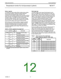
Table 6. Status register bit assignment
POR
STATE
BIT
NAME
FUNCTION
7 (MSB)
BUSY
n/a
High when the ADC is busy
converting
6
IHLF*
ILLF*
EHLF*
ELLF*
OPEN*
n/a
0
0
0
0
0
0
High when the internal
temperature high limit has tripped
Table 7. Alert response bit assignment
(Alert response address = 0001 100)
5
High when the internal
temperature low limit has tripped
ALERT
NAME
RESPONSE ADDRESS
FUNCTION
4
3
High when the external
temperature high limit has tripped
BIT
BIT
7 (MSB)
ADD7
ADD6
ADD5
ADD4
ADD3
ADD2
ADD1
1
Indicate address B6 of alerted device
Indicate address B5 of alerted device
Indicate address B4 of alerted device
Indicate address B3 of alerted device
Indicate address B2 of alerted device
Indicate address B1 of alerted device
Indicate address B0 of alerted device
Logic 1
High when the external
temperature low limit has tripped
6
2
High when the external diode is
opened
5
4
1 to 0
Reserved
3
*
These flags stay high until the status register is read or POR is
activated.
2
1
0 (LSB)
12
1999 Mar 19

 NXP [ NXP ]