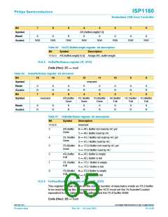
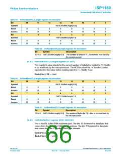
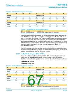
ISP1160
Embedded USB Host Controller
Philips Semiconductors
11. Power supply
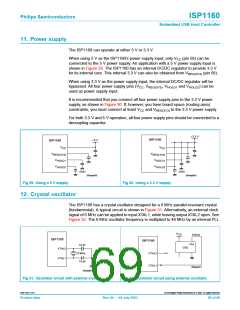
The ISP1160 can operate at either 5 V or 3.3 V.
When using 5 V as the ISP1160’s power supply input, only VCC (pin 56) can be
connected to the 5 V power supply. An application with a 5 V power supply input is
shown in Figure 29. The ISP1160 has an internal DC/DC regulator to provide 3.3 V
for its internal core. This internal 3.3 V can also be obtained from VREG(3V3) (pin 58).
When using 3.3 V as the power supply input, the internal DC/DC regulator will be
bypassed. All four power supply pins (VCC, VREG(3V3), VHOLD1 and VHOLD2) can be
used as power supply input.
It is recommended that you connect all four power supply pins to the 3.3 V power
supply, as shown in Figure 30. If, however, you have board space (routing area)
constraints, you must connect at least VCC and VREG(3V3) to the 3.3 V power supply.
For both 3.3 V and 5 V operation, all four power supply pins should be connected to a
decoupling capacitor.
+3.3 V
ISP1160
+5 V
ISP1160
V
V
CC
CC
V
V
REG(3V3)
REG(3V3)
V
V
HOLD1
HOLD1
V
V
HOLD2
HOLD2
GND
GND
004aaa068
004aaa069
Fig 29. Using a 5 V supply.
Fig 30. Using a 3.3 V supply.
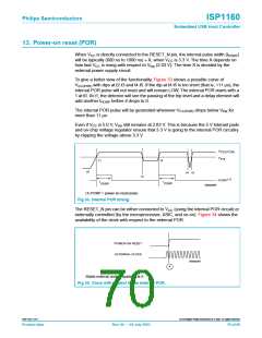
12. Crystal oscillator
The ISP1160 has a crystal oscillator designed for a 6 MHz parallel-resonant crystal
(fundamental). A typical circuit is shown in Figure 31. Alternatively, an external clock
signal of 6 MHz can be applied to input XTAL1, while leaving output XTAL2 open. See
Figure 32. The 6 MHz oscillator frequency is multiplied to 48 MHz by an internal PLL.
V
CC
6 MHz
ISP1160
ISP1160
Out
18 pF
6 MHz
18 pF
OSC
XTAL2
n.c.
XTAL2
XTAL1
XTAL1
004aaa071
004aaa070
Fig 31. Oscillator circuit with external crystal.
Fig 32. Oscillator circuit using external oscillator.
9397 750 11371
© Koninklijke Philips Electronics N.V. 2003. All rights reserved.
Product data
Rev. 04 — 04 July 2003
69 of 88

 NXP [ NXP ]