Philips Semiconductors
Product data
Single wire CAN transceiver
AU5790
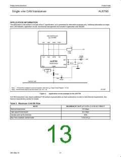
APPLICATION INFORMATION
The information in this section is not part of the IC specification, but is presented for information purposes only. Additional information on single
wire CAN networks, application circuits, and thermal management are included in application note AN2005.
CAN CONTROLLER
(e.g. SJA1000)
PORT
TX0
RX0
PORT
R
D
+5V
2.4 to
2.7kΩ
1N5060
or equiv.
TxD
RxD
NSTB
EN
+12V
BAT
AU5790
TRANSCEIVER
100 nF
1 to 4.7 µF
GND
CANH
RTH
9.1kΩ,
1%
R
T
L
47 µH
C
L
10%
220 pF
CAN BUS LINE
Note 1 TX0 should be configured to push-pull operation, active low; e.g., Output Control Register = 1E hex.
SL01200
Note 2 Recommended range for the load resistor is 3k < R < 11k.
T
Figure 4.
Application circuit example for the AU5790
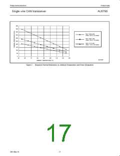
AU5790 transceivers may require additional PCB surface at ground pin(s) as heat conductor(s) in order to meet thermal requirements. See
thermal characteristics section for details.
Table 2. Maximum CAN Bit Rate
MODE
MAXIMUM BIT RATE AT 0.35% CLOCK ACCURACY
Normal transmission
33.3 kbps
83.3 kbps
85%
High-speed transmission
Sample point as % of bit time
Bus Time constant, normal mode
1.0 to 4.0 µs
13
2001 May 18

 NXP [ NXP ]