Philips Semiconductors
Product data
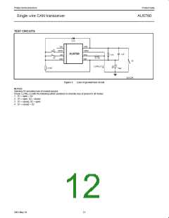
Single wire CAN transceiver
AU5790
Power Dissipation
I
= V
/R
CANHN LOAD
LOAD
Power dissipation of an IC is the major factor determining junction
temperature. AU5790 power dissipation in active and passive states
are different. The average power dissipation is:
I
= I
+ I
LOAD INT
BATN
where:
I
is an active state current dissipated within the IC in
INT
normal mode.
P
tot
= P *Dy + P
* (1-Dy)
INT
PNINT
I
will decrease slightly when the node number
INT
where:
P
P
P
is total dissipation power;
tot
decreases. To simplify this analysis, we will assume I
fixed.
is
INT
is dissipation power in an active state;
INT
is dissipation power in a passive state;
I
= I
(32 nodes) – I
(32 nodes)
LOAD
PNINT
INT
BATN
Dy is duty cycle, which is the percentage of time that TxD
is in an active state during any given time duration.
I
(32 nodes) may be found in the DC Characteristics
BATN
table.
At passive state there is no current going into the load. So
all of the supply current is dissipated inside the IC.
A power dissipation example follows. The assumed values
are chosen from specification and typical applications.
P
PNINT
= V
* I
BAT BATPN
Assumptions:
where:
V
BAT
is the battery voltage;
V
BAT
= 13.4 V
R = 9.1 kΩ
32 nodes
T
I
is the passive state supply current in normal mode.
BATPN
In an active state, part of the supply current goes to the
load, and only part of the supply current dissipates inside
the IC, causing an incremental increase in junction
temperature.
I
= 2 mA
BATPN
I
(32 nodes) = 35 mA
BATN
V
= 4.55 V
CANHN
Duty cycle = 50%
P
INT
= P
– P
LOADN
Computations:
BATAN
where:
where:
P
is active state battery supply power in normal
R
= 9.1 kΩ / 32 = 284.4 Ω
BATAN
LOAD
mode;
P
I
P
= 13.4 V × 2 mA = 26.8 mW
= 4.55 V / 284.4 Ω = 16mA
= 4.55 V × 16 mA = 72.8 mW
= 35 mA - 16 mA = 19 mA
= 13.4 V × 35 mA = 469 mW
PNINT
LOAD
P
BATAN
= V
* I
BAT BATAN
LOADN
P
is load power consumption in normal mode.
I
LOADN
INT
P
BATAN
P
= V
* I
CANHN LOADN
LOADN
P
= 469 mW - 72.8 mW = 396.2 mW
INT
P
tot
= 396.2 mW × 50% + 26.8 mW × (1-50%) = 211.5 mW
I
is active state supply current in normal mode;
BATAN
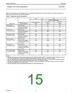
Additional examples with various node counts are shown in Table 4.
V
is bus output voltage in normal mode;
CANHN
I
is current going through load in normal mode.
LOADN
Table 4. Representative Power Dissipation Analyses
R
I
P
PNINT
V
I
I
P
INT
P
tot
LOAD
BATPN
CANHN
LOAD
BATN
Nodes
2
(Ω)
V
BAT
(V)
(mA)
(mW)
26.8
26.8
26.8
26.8
53
(V)
(mA)
(mA)
I
(mA)
(mW)
263.5
298.9
343.1
396.2
525.5
613.3
723
Dcycle
0.5
(mW)
145.1
162.8
184.9
211.5
289.2
333.1
388
INT
4550
910
13.4
13.4
13.4
13.4
26.5
26.5
26.5
26.5
2
2
2
2
2
2
2
2
4.55
4.55
4.55
4.55
4.55
4.55
4.55
4.55
1
20
19
10
20
32
2
5
24
19
19
19
19
19
19
19
0.5
455
10
16
1
29
0.5
284.4
4550
910
35
0.5
20
0.5
10
20
32
53
5
24
0.5
455
53
10
16
29
0.5
284.4
53
35
854.7
0.5
453.8
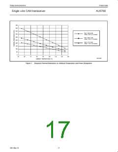
By knowing the maximum power dissipation, and the operation ambient temperature, the required thermal resistance without tripping the
thermal protection can be calculated, as shown in Figure 7. Then from Figure 5 or 6, a suitable PCB can be selected.
16
2001 May 18

 NXP [ NXP ]