AN8026
Voltage Regulators
■ Application Notes (continued)
[2] Operation descriptions
1. Start/stop circuit block
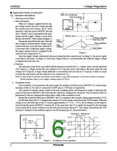
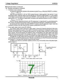
• Start mechanism
After AC rectificatio
Start resistance
R1
VCC
When AC voltage is applied and the sup-
C8
VOUT
GND
ply voltage reaches the start voltage through
the current from start resistor, the IC starts
operation. Then the power MOSFET driving
starts. Thereby, bias is generated in the trans-
former and the supply voltage is given from
the bias coil to the IC. (This is point a in figure 1.)
During the period from the time when the
start voltage is reached and the voltage is gen-
erated in the bias coil to the time when the IC
is provided with a sufficient supply voltage,
the supply voltage of the IC is supplied by the
Before start
Start
Voltage supplied
from bias coil
a
Start
voltage
Start condition
Stop
voltage
b
c
Start failure
Figure 1
capacitor (C8) connected to VCC
.
Since the supply voltage continuously decreases during the above period (area b in figure 1), the power supply
is not able to start (state c in figure 1), if the stop voltage of the IC is reached before the sufficient supply voltage
is supplied from the bias coil.
• Function
The start/stop circuit block is provided with the function to monitor the VCC voltage, and to start the operation
of IC when VCC voltage reaches the start voltage (14.9 V typical), and to stop when it decreases under the stop
voltage (8.6 V typical). A large voltage difference is set between start and stop (6.3 V typical), so that it is easier
to select the start resistor and the capacitor to be connected to VCC
.
Note) To start up the IC operation, the startup current which is a pre-start current plus a circuit drive current is necessary.
Set the resistance value so as to supply a startup current of 350 µA.
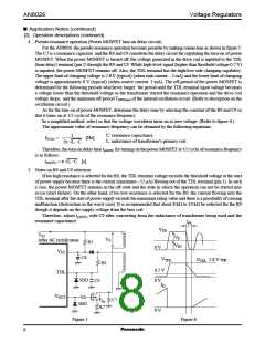
2. Oscillation circuit
The oscillation circuit generates the pulse signal for turning on/off the power MOSFET by using charge/
discharge of the C2, R2 and C3 connected to TOFF (pin 2), TON (pin 3) respectively.
The concept of constant voltage control at the time of making up the switching power supply is fixing the off-
period of the power MOSFET and achieving the control by changing the on-period. This on-period control is
performed by directly changing the output pulse width of the oscillation circuit.
During the on-period of the power MOSFET, the C2 is charged to the constant voltage (approximately 0.9 V).
On the other hand, the C3 is charged from almost 0 V by the charge current from the TON terminal. When the
voltage across the both ends of the C3 reaches approximately 0.7 V (Ta = 75°C), the oscillation circuit output is
reversed and the power MOSFET is turned off. At the same time, the C3 is rapidly discharged by the discharge
circuit inside the IC and its voltage across the both ends becomes almost 0 V. The charge current from the TON
terminal is changed by the feedback signal to the FB terminal (pin 9). (Described later.)
On-period Off-period
0.9 V
Voltage across
both ends of C2
200 Ω
0.1 V
0.7 V
Voltage across
both ends of C3
0 V
IC output
R2
C3 C2
0 V
Figure 2. Oscillation circuit operation
6

 PANASONIC [ PANASONIC ]