AN8026
Voltage Regulators
■ Application Notes (continued)
[2] Operation descriptions (continued)
7. Overvoltage protection circuit (OVP) (continued)
• Operating supply current characteristics
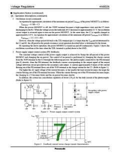
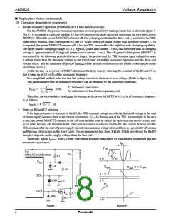
While the OVP is operating, the decrease of the supply current causes the rise of the supply voltage VCC , and
in the worst case, the guaranteed breakdown voltage of the IC (35 V) can be exceeded. In order to prevent the rise
of supply voltage, the IC is provided with such characteristics as that the supply current rises in the constant
resistance mode. This characteristics ensure that the OVP can not be released unless the AC input is cut, if the
supply voltage VCC under OVP operating has been stabilized over the OVP release supply voltage (which depends
on start resistor selection). (Refer to figure 9.)
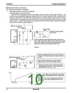
After AC rectification
Start resistor
R1
Power supply
output
VCC
Abnormal voltage applied
from outside
FRD
Load
OVP
It detects abnormal voltage applied from the outside to the
power supply output (the voltage which is higher than voltage
of the power supply output and may damage the load) by the
primary side of the bias coil and operates the OVP.
VOUT
GND
Figure 8
The current supply from the start resistor continues
as long as the voltage of the power supply input (AC)
is given.
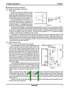
After AC rectification
Start resistor
R1
After OVP starts operation, since the output is
stopped, this bias coil does not supply current.
VCC
* Select the resistance value so that the following
relationship can be kept by current supply from
the start resistor: VCC >VCC− OVP
VOUT
GND
ICC
At VCC− OVP (voltage under which OVP is released)
as the boundary, the operating current is temporarily
increased.
This prevents VCC from exceeding the break down
voltage due to the current supplied from the above
start resistor.
VCC− OVP
VCC
Figure 9
10

 PANASONIC [ PANASONIC ]