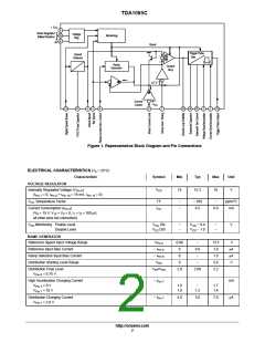
TDA1085C
Tachogenerator Circuit
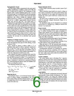
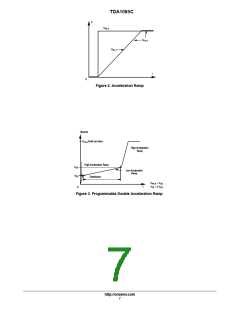
Ramps Generator (Pin 6)
The tacho signal voltage is proportional to the motor speed.
Stability considerations, in addition, require an RC filter, the
pole of which must be looked at. The combination of both
elements yield a constant amplitude signal on Pin 12 in most
of the speed range. It is recommended to verify this maximum
amplitude to be within 1.0 V peak in order to have the largest
signal/noise ratio without resetting the integrated circuit
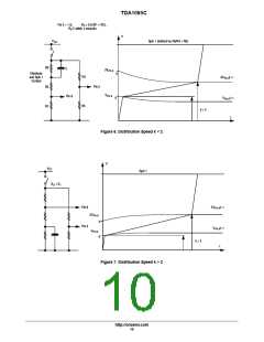
If only a high acceleration ramp is needed, connect Pin 6
to ground.
When a Distribute ramp should occur, preset a voltage on
Pin 6 which corresponds to the motor speed starting ramp
point. Distribution (or low ramp) will continue up to the
moment the motor speed would have reached twice the
starting value.
(which occurs if V
reaches 5.5 V). It must be also verified
The ratio of two is imposed by the IC. Nevertheless, it
could be externally changed downwards (Figure 6) or
upwards (Figure 7).
Pin 12
that the Pin 12 signal is approximately balanced between
“high” (over 300 mV) and “low”. An 8−poles tacho is a
minimum for low speed stability and a 16−poles is even better.
The RC pole of the tacho circuit should be chosen within
30 Hz in order to be as far as possible from the 150 Hz which
corresponds to the AC line 3rd harmonic generated by the
motor during starting procedure. In addition, a high value
The distribution ramp can be shortened by an external
resistor from V charging C
, adding its current to the
CC
Pin 7
internal 5.0 mA generator.
Power Circuits
Triac Triggering pulse amplitude must be determined by
Pin 13 resistor according to the needs in Quadrant IV.
Trigger pulse duration can be disturbed by noise signals
generated by the triac itself, which interfere within Pins 14
and 16, precisely those which determine it. While easily
visible, this effect is harmless.
The triac must be protected from high AC line dV/dt during
external disturbances by 100 nF x 100 W network.
Shunt resistor must be as non−inductive as possible. It can
be made locally by using constantan alloy wire.
resistor coming from V introduces a positive offset at Pin
CC
12, removes noise to be interpreted as a tacho signal. This
offset should be designed in order to let Pin 12 reach at least
− 200 mV (negative voltage) at the lowest motor speed. We
remember the necessity of an individual tacho ground
connection.
Frequency to Voltage Converter − F V/C
C
Pin
11 has a recommended value of 820 pF for 8−poles
tachos and maximum motor rpm of 15000, and R 11 must
Pin
be always 470 K.
When the load is a DC fed universal motor through a
rectifier bridge, the triac must be protected from commutating
R
Pin 4
should be chosen to deliver within 12 V at
maximum motor speed in order to maximize signal/noise
ratio. As the FV/C ratio as well as the C value are
dV/dt by a 1.0 to 2.0 mH coil in series with MT .
2
Synchronization functions are performed by resistors
sensing AC line and triac conduction. 820 k values are
normal but could be reduced down to 330 k in order to detect
the “zeros” with accuracy and to reduce the residual DC line
component below 20 mA.
Pin 11
dispersed, R
must be adjustable and should be made of
Pin 4
a fixed resistor in service with a trimmer representing 25%
of the total. Adjustment would become easier.
Once adjusted, for instance at maximum motor speed, the
FV/C presents a residual non linearity; the conversion factor
(mV per RPM) increases by within 7.7% as speed draws to
zero. The guaranteed dispersion of the latter being very
narrow, a maximum 1% speed error is guaranteed if during
Pin 5 network design the small set values are modified, once
forever, according this increase.
Current Limitation
The current limiter starts to discharge Pin 7 capacitor
(reference speed) as the motor current reaches the designed
threshold level. The loop gain is determined by the resistor
connecting Pin 3 to the series shunt. Experience has shown
that its optimal value for a 10 Arms limitation is within
2.0 kW. Pin 3 input has a sensitivity in current which is
limited to reasonable values and should not react to spikes.
If not used, Pin 3 must be connected to a maximum
positive voltage of 5.0 V rather than be left open.
The following formulas give V
:
Pin 4
1
V
+ G.0 @ (V –V ) @ C
@ R @ f @
In volts.
a
4
11
Pin
4
Pin
CC
120k
R
(1 )
)
Pin11
.
G.0 (V − V ) ] 140
CC
a
V = 2.0 V
a
BE
120 k = R , on Pin 11
int
Loop Stability
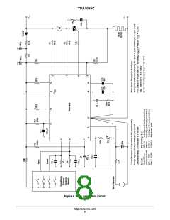
The Pin 16 network is predominant and must be adjusted
experimentally during module development. The values
indicated in Figure 4 are typical for washing machine
applications but accept large modifications from one model
to another. R16 (the sole restriction) should not go below
33 k, otherwise slew rate limitation will cause large transient
errors for load steps.
Speed Set (Pin 5)
Upon designer choice, a set of external resistors apply a
series of various voltages corresponding to the various
motor speeds. When switching external resistors, verify that
no voltage below 80 mV is ever applied to Pin 5. If so, a full
circuit reset will occur.
http://onsemi.com
6

 ONSEMI [ ONSEMI ]