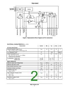
TDA1085C
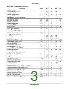
ELECTRICAL CHARACTERISTICS (continued)
Characteristic
Symbol
Min
Typ
Max
Unit
CURRENT LIMITER
Limiter Current Gain — I
/I
C
130
50
180
65
250
80
Pin 7 Pin 3
g
(I
= − 300 mA)
Pin3
Detection Threshold Voltage
= − 10 mA
V
mV
Pin 3 TH
I
Pin 3
FREQUENCY TO VOLTAGE CONVERTER
Input Signal “Low Voltage”
Input Signal “High Voltage”
Monitoring Reset Voltage
V
−100
+100
5.0
−
−
−
−
−
−
mV
mV
V
12 L
12 H
12 R
V
V
Negative Clamping Voltage
− V
−
0.6
−
V
12 CL
I
= − 200 mA
Pin 12
Input Bias Current
− I
−
25
−
−
mA
Pin12
Internal Current Source Gain
G.0
9.5
11
I
Pin 4
G +
, V
+ V
+ 0
Pin 4
Pin 11
I
Pin 11
Gain Linearity versus Voltage on Pin 4
(G = Gain for V = 8.6 V)
G/G
8.6
8.6
Pin 4
V = 0 V
1.04
1.015
0.965
1.05
1.025
0.975
1.06
1.035
0.985
4
V = 4.3 V
4
V = 12 V
4
Gain Temperature Effect (V
= 0)
= 0)
TF
−
0
350
−
−
ppm/°C
Pin 4
Output Leakage Current (I
− I
Pin 4
100
nA
Pin 11
CONTROL AMPLIFIER
Actual Speed Input Voltage Range
V
0
0
−
−
13.5
50
V
Pin 4
Input Offset Voltage V − V
V
off
mV
Pin 5
Pin 4
(I
= 0, V
= 3.0 and 8.0 V)
Pin 16
Pin 16
Amplifier Transconductance
T
270
340
400
mA/V
mA
(I
(I
/D (V − V )
5 4
Pin 16
Pin 16
= + and − 50 mA, V
= 3.0 V)
Pin 16
Output Current Swing Capability
I
Pin 16
Source
Sink
− 200
50
− 100
100
− 50
200
Output Saturation Voltage
V
−
−
0.8
V
16 sat
TRIGGER PULSE GENERATOR
Synchronization Level Currents
Voltage Line Sensing
Triac Sensing
mA
I
I
−
−
50
50
100
100
Pin 2
Pin 1
Trigger Pulse Duration (C
= 47 nF, R
= 270 kW)
T
−
−
55
220
192
−
−
−
ms
ms
mA
mA
V
Pin 14
Pin 15
p
Trigger Pulse Repetition Period, conditions as a.m.
Output Pulse Current V = V − 4.0 V
T
R
− I
180
−
−
Pin 13
CC
Pin 13
13 L
Output Leakage Current V
= − 3.0 V
I
30
−
Pin 13
Full Angle Conduction Input Voltage
Saw Tooth “High” Level Voltage
V
−
11.7
−
14
V
12
90
12.7
105
V
14 H
Saw Tooth Discharge Current, I
= 100 mA
I
−
mA
Pin15
Pin 14
http://onsemi.com
3

 ONSEMI [ ONSEMI ]