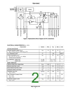
TDA1085C
As the voltages applied by Pins 5 and 6 are derived from
• The repetition of the pulse if the triac fails to latch on if
the current has been interrupted by brush bounce.
• The delay of firing pulse until the current crosses zero
at wide firing angles and inductive loads.
the internal voltage regulator supply and Pin 4 voltage is
also derived from the same source, motor speed (which is
determined by the ratios between above mentioned
voltages) is totally independent from V variations and
CC
R
Pin 15
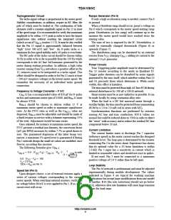
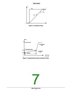
programs the Pin 14 discharging current. Saw
temperature factor.
tooth signal is then fully determined by R15 and C14
(usually 47 nF). Firing pulse duration and repetition period
are in inverse ratio to the saw tooth slope.
Pin 13 is the pulse output and an external limiting resistor
is mandatory. Maximum current capability is 200 mA.
Control Amplifier (Pin 16)
It amplifies the difference between true speed (Pin 4) and
set speed (Pin 5), through the ramp generator. Its output
available at Pin 16 is a double sense current source with a
maximum capability of
100 mA and a specified
Current Limiter (Pin 3)
transconductance (340 mA/V typical). Pin 16 drives directly
the trigger pulse generator, and must be loaded by an
electrical network which compensates the mechanical
characteristics of the motor and its load, in order to provide
stability in any condition and shortest transient response; see
Figure 4.
This network must be adjusted experimentally.
In case of a periodic torque variations, Pin 16 directly
provides the phase angle oscillations.
Safe operation of the motor and triac under all conditions
is ensured by limiting the peak current. The motor current
develops an alternative voltage in the shunt resistor (0.05 W
in Figure 4). The negative half waves are transferred to Pin
3 which is positively preset at a voltage determined by
resistors R3 and R4. As motor current increases, the
dynamical voltage range of Pin 3 increases and when Pin 3
becomes slightly negative in respect to Pin 8, a current
starts to circulate in it. This current, amplified typically 180
times, is then used to discharge Pin 7 capacitor and, as a
result, reduces firing angle down to a value where an
equilibrium is reached. The choice of resistors R3, R4 and
shunt determines the magnitude of the discharge current
Trigger Pulse Generator (Pins 1, 2, 5, 13, 14, 15)
This circuit performs four functions:
• The conversion of the control amplifier DC output
level to a proportional firing angle at every main line
half cycle.
• The calibration of pulse duration.
signals on C
.
Pin 7
Notice that the current limiter acts only on peak triac
current.
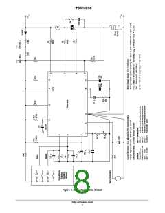
APPLICATION NOTES
(Refer to Figure 4)
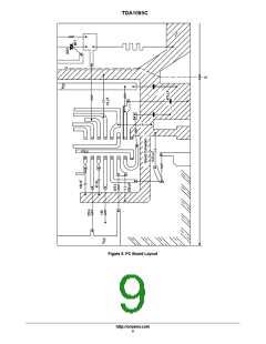
Printed Circuit Layout Rules
As an example, Figure 5 presents a PC board pattern
which concerns the group of sensitive Pins and their
associated capacitors into which the a.m. rules have been
implemented. Notice the full separation of “Signal World”
from “Power”, one by line AB and their communication by
a unique strip.
In the common applications, where TDA 1085C is used,
there is on the same board, presence of high voltage, high
currents as well as low voltage signals where millivolts
count. It is of first magnitude importance to separate them
from each other and to respect the following rules:
These rules will lead to much satisfactory volume
production in the sense that speed adjustment will stay
valid in the entire speed range.
• Capacitor decoupling pins, which are the inputs of the
same comparator, must be physically close to the IC,
close to each other and grounded in the same point.
• Ground connection for tachogenerator must be directly
connected to Pin 8 and should ground only the tacho. In
effect, the latter is a first magnitude noise generator due
to its proximity to the motor which induces high dφ/dt
signals.
Power Supply
As dropping resistor dissipates noticeable power, it is
necessary to reduce the I needs down to a minimum.
CC
Triggering pulses, if a certain number of repetitions are kept
in reserve to cope with motor brush wearing at the end of its
• The ground pattern must be in the “star style” in order
to fully eliminate power currents flowing in the ground
network devoted to capacitors decoupling sensitive
Pins: 4, 5, 7, 11, 12, 14, 16.
life, are the largest I
configuration has to be considered to select dropping
resistor. In addition, the parallel regulator must be always
user. Classical worst case
CC
into its dynamic range, i.e., I
over 1.0 mA and V
Pin 10
Pin 10
over 3.0 V in any extreme configuration. The double
filtering cell is mandatory.
http://onsemi.com
5

 ONSEMI [ ONSEMI ]