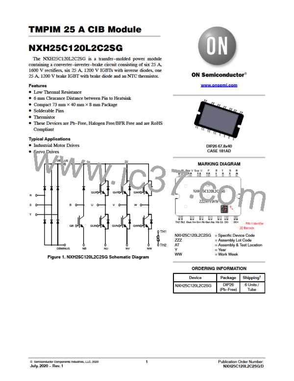
NXH25C120L2C2SG
MAXIMUM RATINGS
Rating
Symbol
Value
Unit
IGBT
Collector−Emitter Voltage
Gate−Emitter Voltage
V
1200
20
V
V
A
A
CES
V
GE
Continuous Collector Current @ T = 80°C (Tv
= 175°C)
= 175°C)
= 150°C)
I
C
25
C
Jmax
Jmax
Jmax
Pulsed Collector Current
DIODE
I
75
Cpulse
Peak Repetitive Reverse Voltage
V
RRM
1200
25
V
A
A
Continuous Forward Current @ T = 80°C (Tv
I
F
C
Repetitive Peak Forward Current
RECTIFIER DIODE
I
75
FRM
Peak Repetitive Reverse Voltage
V
RRM
1600
25
V
A
A
Continuous Forward Current @ T = 80°C (Tv
I
F
C
Repetitive Peak Forward Current
I
75
FRM
2
2
2
I t value (10 ms single half−sine wave) @ 25°C
(10 ms single half−sine wave) @ 150°C
I t
680
360
A t
Surge current (10 ms sin180°) @ 25°C
THERMAL PROPERTIES
Storage Temperature range
INSULATION PROPERTIES
Isolation test voltage, t = 1 sec, 50 Hz
Internal isolation
IFSM
370
−40 to 125
3000
A
T
stg
°C
V
is
V
RMS
Al O
2
3
Creepage distance
6.0
6.0
mm
mm
Clearance distance
Comperative Tracking Index
CTI
> 400
Stresses exceeding those listed in the Maximum Ratings table may damage the device. If any of these limits are exceeded, device functionality
should not be assumed, damage may occur and reliability may be affected.
1. Refer to ELECTRICAL CHARACTERISTICS, RECOMMENDED OPERATING RANGES and/or APPLICATION INFORMATION for Safe
Operating parameters.
www.onsemi.com
2

 ONSEMI [ ONSEMI ]