NCP1399AA, NCP1399BA, NCP1399AC
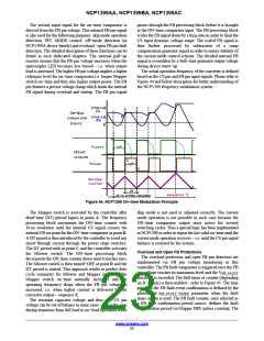
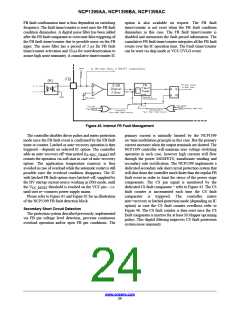
FB fault confirmation time is thus dependent on switching
option is also available on request. The FB fault
timer/counter is not reset when the FB fault condition
diminishes in this case. The FB fault timer/counter is
disabled and memorizes the fault period information. The
cumulative FB fault timer/counter integrates all the FB fault
events over the IC operation time. The Fault timer/counter
can be reset via skip mode or VCC UVLO event.
frequency. The fault timer/counter is reset once the FB fault
condition diminishes. A digital noise filter has been added
after the FB fault comparator to overcome false triggering of
the FB fault timer/counter due to possible noise on the FB
input. The noise filter has a period of 2 ms for FB fault
timer/counter activation and 20 ms for reset/deactivation to
assure high noise immunity. A cumulative timer/counter IC
Figure 45. Internal FB Fault Management
The controller disables driver pulses and enters protection
mode once the FB fault event is confirmed by the FB fault
timer or counter. Latched or auto−recovery operation is then
triggered – depends on selected IC option. The controller
primary current is naturally limited by the NCP1399
on−time modulation principle in this case. But the primary
current increases when the output terminals are shorted. The
NCP1399 controller will maintain zero voltage switching
operation in such case, however high currents will flow
through the power MOSFETS, transformer winding and
secondary side rectification. The NCP1399 implements a
dedicated secondary side short circuit protection system that
will shut down the controller much faster than the regular FB
fault event in order to limit the stress of the power stage
components. The CS pin signal is monitored by the
dedicated CS fault comparator − refer to Figure 43. The CS
fault counter is incremented each time the CS fault
comparator is triggered. The controller enters
auto−recovery or latched protection mode (depending on IC
option) in case the CS fault counter overflows refer to
Figure 46. The CS fault counter is then reset once the CS
fault comparator is inactive for at least 50 Mupper upcoming
pulses. This digital filtering improves CS fault protection
system noise immunity.
adds an auto−recovery off−time period (t ) and
A−REC_TIMER
restarts the operation via soft start in case of auto−recovery
option. The application temperature runaway is thus
avoided in case of overload while the automatic restart is still
possible once the overload condition disappears. The IC
with latched FB fault option stays latched−off, supplied by
the HV startup current source working in DSS mode, until
the V
threshold is reached on the VCC pin – i.e.
CC_RESET
until user re−connects power supply mains.
Please refer to Figure 61 and Figure 62 for an illustration
of the NCP1399 FB fault detection block.
Secondary Short Circuit Detection
The protection system described previously, implemented
via FB pin voltage level detection, prevents continuous
overload operation and/or open FB pin conditions. The
www.onsemi.com
24

 ONSEMI [ ONSEMI ]