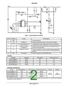
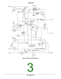
NCP1251
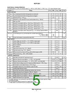
ELECTRICAL CHARACTERISTICS
(For typical values T = 25°C, for min/max values T = −40°C to +125°C, Max T = 150°C, V = 12 V unless otherwise noted)
J
J
J
CC
Symbol
INTERNAL OSCILLATOR
Rating
Pin
Min
Typ
Max
Unit
f
f
Oscillation frequency (65 kHz version)
Oscillation frequency (100 kHz version)
Maximum duty−cycle
−
−
−
−
−
61
92
76
65
100
80
71
108
84
kHz
kHz
%
OSC
OSC
D
max
f
Frequency jittering in percentage of f
Swing frequency
5
%
jitter
OSC
f
240
Hz
swing
FEEDBACK SECTION
R
R
Internal pull−up resistor
2
2
−
2
20
16
kW
kW
up
eq
Equivalent ac resistor from FB to GND
I
Pin 2 to current setpoint division ratio
4.2
1.05
ratio
V
freeze
Feedback voltage below which the peak current is frozen
V
FREQUENCY FOLDBACK
V
Frequency foldback level on the feedback pin – [45% of maximum peak current
Transition frequency below which skip−cycle occurs
−
−
1.5
26
V
fold
F
trans
22
30
kHz
mV
mV
mV
V
End of frequency foldback feedback leve, F = F
min
350
300
30
fold,end
sw
V
skip
Skip−cycle level voltage on the feedback pin
−
−
Skip
hysteresis
Hysteresis on the skip comparator – (Note 5)
INTERNAL SLOPE COMPENSATION
V
Internal ramp level @ 25°C – (Note 7)
4
4
2.5
20
V
ramp
R
Internal ramp resistance to CS pin
kW
ramp
PROTECTIONS
V
Latching level input
3
1
−
1
−
5
5
2.7
3
3.3
V
latch
T
T
Blanking time after drive turn off
Number of clock cycles before latch confirmation
OVP detection time constant
1.0
4.0
600
130
25.5
20
ms
latch−blank
latch−count
T
ns
ms
V
latch−del
Timer
Internal auto−recovery fault timer duration
100
24
160
27
V
Latched Over voltage protection on the V rail
CC
OVP
T
Delay before OVP on V confirmation
ms
OVPdel
CC
4. For design robustness, we recommend to inject 60 mA as a minimum at the lowest input line voltage.
5. Guaranteed by design
6. See characterization table for linearity over negative bias voltage
7. A 1 MW resistor is connected from pin 3 to the ground for the measurement.
http://onsemi.com
6

 ONSEMI [ ONSEMI ]