NCP1251
D2
1N4148
NT C
ROPPU
841k
VCC
au x.
winding
OP P
ROPPL
2.5k
full−latch
OPP
Vlatch
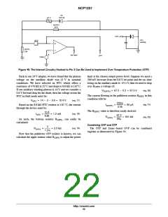
Figure 49. The Internal Circuitry Hooked to Pin 3 Can Be Used to Implement Over Temperature Protection (OTP)
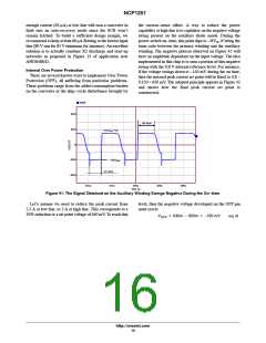
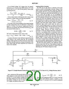
Back to our 19 V adapter, we have found that the plateau
voltage on the auxiliary diode was 13 V in nominal
conditions. We have selected an NTC which offers a
resistance of 470 kW at 25°C and drops to 8.8 kW at 110°C.
If our auxiliary winding plateau is 14 V and we consider a
0.6 V forward drop for the diode, then the voltage across the
NTC in fault mode must be:
limit at the chosen output power level. Suppose we need a
200 mV decrease from the 0.8 V set point and the on−time
swing on the auxiliary anode is −67.5 V, then we need to drop
over R
a voltage of:
OPPU
VROPPU + 67.5 * 0.2 + 67.3 V
(eq. 20)
The current flowing in the pulldown resistor R
in this
OPPL
condition will be:
VNTC + 14 * 3 * 0.6 + 10.4 V
(eq. 17)
200m
(eq. 21)
(eq. 22)
Based on the 8.8 kW NTC resistor at 110 °C, the current
through the device must be:
IROPPU
+
+ 80 mA
2.5k
The R
value is therefore easily derived:
OPPU
10.4
(eq. 18)
INTC
+
[ 1.2 mA
67.3
8.8k
ROPPU
+
+ 841 kW
80m
As such, the bottom resistor R
calculated:
, can easily be
OPPL
Combining OVP and OTP
The OTP and Zener−based OVP can be combined
together as illustrated by Figure 50.
3
(eq. 19)
ROPPL
+
+ 2.5 kW
1.2m
Now that the pulldown OPP resistor is known, we can
calculate the upper resistor value R to adjust the power
OPPU
http://onsemi.com
22

 ONSEMI [ ONSEMI ]