NCP1239
APPLICATION INFORMATION
The NCP1239 includes all necessary features to help
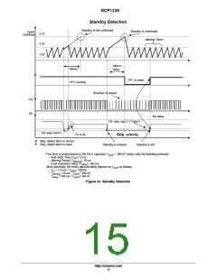
detected mode (standby or normal mode). Simply connect a
pnp transistor between the NCP1239 V and the PFC
controller one and drive it using Pin 1, to enable the PFC
stage in normal mode and disable it in standby.
building a rugged and safe switch−mode power supply. The
following details the major benefits brought by
implementing the NCP1239 controller:
CC
Current−mode operation with internal ramp
compensation: implementing peak current mode control,
the NCP1239 offers an internal ramp compensation signal
that can easily be summed up to the sensed current.
Subharmonic oscillations can thus be fought via the
inclusion of a simple resistor,
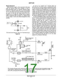
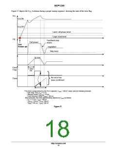
Soft−Start: the capacitor connected to Pin 6 provides a
soft−start sequence that precludes the main power switch
from being stressed upon startup. The same voltage is also
used to perform frequency jittering and timing for the fault
condition detection.
Major Fault Detection: the circuit detects when Pin 3
voltage exceeds 2.4 V. When this occurs, the NCP1239
considers that a major fault is present and as a consequence,
the circuit gets permanently latched−off. In this mode, the
500 mV Current Sense threshold for Over Power Limit
(NCP1239F): the NCP1239 operating in current mode, the
circuit Pin 10 monitors the current to modulate its level
according to the power demand. Due to the ramp
compensation, one must generally note that the Pin 10
voltage is not the exact image of the inductor current. A
precise current limitation being essential, the NCP1239
features a separate current sense pin (Pin 9) for an accurate
overcurrent detection. The low threshold of this protection
(500 mV) avoids excessive losses in the current sense
resistor and improves the efficiency. In addition, Pin 9
sources a current that proportional to the high−voltage rail,
compensates the current−sense and turn off delays at high
line. A resistor inserted between Pin 9 and the sensing
resistor offsets the Pin 9 current−sense information to build
a precise overload protection, independent of the mains
input.
circuit needs the V to go down below 4.0 V to reset, for
CC
instance when the user un−plugs the SMPS. This capability
is mainly intended to detect an overvoltage condition or/and
an over−heating of the application that would be sensed by
a thermistor.
Brown−out detection: by monitoring the level on Pin 5
during normal operation, the controller protects the SMPS
against low mains conditions. When the Pin 5 voltage falls
below 250 mV, the controllers stops pulsing until this level
goes back to 500 mV to prevent any instability.
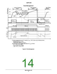
Short−circuit protection: short−circuit and especially
overload protections are difficult to implement when a
strong leakage inductance affects the transformer (the
auxiliary winding level does not properly collapse…). Here,
every time the feedback pin is at its maximum (higher than
5.0 V practically), an error flag is asserted and the circuit
activates a timer that is programmed by the Pin 6 capacitor.
If Pin 6 reaches 4.3 V while the error flag is still present, the
controller stops the pulses and goes into a latch−off phase,
operating in a low−frequency burst−mode. As soon as the
fault disappears, the SMPS resumes its operation. The
latch−off phase can also be initiated, more classically, when
Large V operation: the NCP1239 offers an extended
CC
V
CC
range up to 36 V, bringing greater flexibility in Flyback
or Forward applications.
Internal high−voltage startup switch: reaching low
levels of standby power represents a difficult exercise when
the controller requires an external, lossy, resistor connected
to the bulk capacitor. Due to an internal logic, the controller
disables the high−voltage current source after startup which
no longer hampers the consumption in no−load situations.
Skip−cyclecapability: a continuous flow of pulses is not
compatible with no−load standby power requirements.
Slicing the switching pattern in bunch of pulses drastically
reduces overall losses but can, in certain cases, bring
acoustic noise in the transformer. Due to a skip operation
taking place at low peak currents only, no mechanical noise
appears in the transformer. Furthermore, the skip threshold
is made programmable to allow the best trade−off between
noise and efficiency.
V
CC
drops below UVLO (11.2 V typical).
Adjustable frequency and Internal dithering for
improved EMI signature: Pin 4 offers a means to precisely
adjust the switching frequency through a simple resistor to
ground. Frequency operation is allowed up to 250 kHz. By
modulating the internal switching frequency with the Pin 6
saw−tooth (100 Hz with 390 nF), natural energy spread
appears and softens the controller’s EMI signature.
5.0 V reference voltage: a 5.0 V regulator is provided to
help biasing any external circuitry in the vicinity of the
controller. This reference voltage can typically supply up to
10 mA.
Standby Detect/Shutdown of the PFC front−stage: The
NCP1239 incorporates an internal logic that is able to detect
a standby situation. Pin1 state changes in accordance to the
http://onsemi.com
16

 ONSEMI [ ONSEMI ]