NCP1239
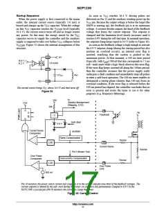
Startup Sequence
As soon as V
reaches 16.4 V, driving pulses are
CC
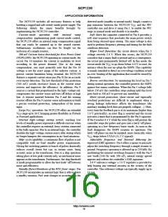
When the power supply is first connected to the mains
outlet, the internal current source (typically 3.6 mA) is
delivered on Pin 12 and the auxiliary winding grows up the
pin. Because the output voltage is below the target (the
V
CC
biased and charges up the V capacitor. When the voltage
SMPS is starting up), the feedback pin is at its maximum
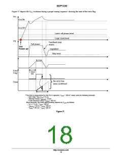
voltage. A resistor divider outputs the third of the feedback
voltage that forms the current setpoint. This setpoint is
clamped and the limitation level slowly increases until it
reaches 0.9V during the soft start time. In nominal operation,
the setpoint clamp keeps equal to 0.9 V (refer to Figure 36).
As soon as the feedback voltage is high enough to activate
the 0.9 V setpoint clamp (during the startup period but also
anytime an overload occurs), an internal error flag is
asserted, testifying that the system is pushed to the
maximum power. At that moment, a 100 ms time period
CC
on this V capacitor reaches the V
level (typically
CC
CCON
16.4 V), the current source turns off and no longer wastes
any power. At this time, the energy stored by the V
CC
capacitor serves to supply the controller and the auxiliary
supply is supposed to take over before V collapses below
CC
V . Figure 35 shows the internal arrangement of this
CCOFF
structure:
16
13
10
HV
16.4 V /
11.2 V
(typically, with C =390 nF that also corresponds to 7.5 ms
pin6
+
−
3.6 mA/0
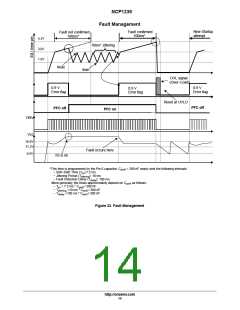
soft −start) starts while a logic block observes this error flag.
If the error flag keeps asserted all along the 100ms period,
then the controller assumes that the power supply really
undergoes a fault condition and immediately stops all pulses
to enter a safe burst operation. The 100 ms timer enables to
distinguish a startup phase (shorter than 100 ms) from an
overload condition. If the error flag is released before the
100 ms period has elapsed, the controller concludes that no
error is present and resets the timer to use it for other
purposes (e.g. frequency dithering).
CV
Aux
CC
The current source brings VCC above 16.4 V and then turns off
Figure 35.
to
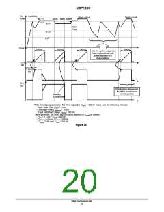
Vdd
/ 3
Standby Management
(Skipping, GTS)
CLK
S
20k
8
Q
Q
Vin
Feedback
R
Soft−Start
oscillator
0.9 V
Current Sense
Comparator
−
+
Ramp Compensation
Rramp
Rcomp
LEB
LEB
10
Current Sense
Rsense
Pin 5 (Brown−Out)
Overcurrents Compensation
Over Power
Comparator
9
+
−
Over Power
Limit
+
500 mV
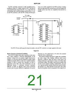
Pin 10 monitors the power switch current and compares it to the current setpoint (one third of the feedback voltage). The
current setpoint is limited by the soft−start during the power−on sequence and permanently clamped to 0.9 V In the
NCP1239F, a second pin (Pin 9) monitors the current to clamp the power.
Figure 36. Current Control
http://onsemi.com
17

 ONSEMI [ ONSEMI ]