NCP1200A
V
CC
REGULATION
OCCURS
HERE
12 V
LATCHOFF
PHASE
10 V
5.4 V
TIME
TIME
TIME
Drv
DRIVER
PULSES
DRIVER
PULSES
INTERNAL
FAULT FLAG
FAULT IS
RELAXED
FAULT OCCURS HERE
STARTUP PHASE
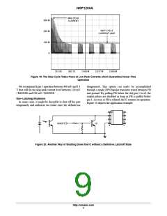
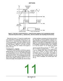
Figure 21. If the fault is relaxed during the VCC natural fall down sequence, the IC automatically resumes.
If the fault still persists when VCC reached UVLOL, then the controller cuts everything off until recovery.
When this level crosses 5.4 V typical, the controller enters
a new startup phase by turning the current source on: V
in either simulating or measuring in the lab how much time
the system takes to reach the regulation at full load. Let’s
CC
rises toward 12 V and again delivers output pulses at the
UVLO crossing point. If the fault condition has been
suppose that this time corresponds to 6 ms. Therefore a V
CC
fall time of 10 ms could be well appropriated in order to not
trigger the overload detection circuitry. If the corresponding
IC consumption, including the MOSFET drive, establishes
at 1.8 mA for instance, we can calculate the required
H
removed before UVLO approaches, then the IC continues
L
its normal operation. Otherwise, a new fault cycle takes
place. Figure 21 shows the evolution of the signals in
presence of a fault.
DV @ C
Dt +
capacitor using the following formula:
, with
i
Calculating the VCC Capacitor
As the above section describes, the fall down sequence
DV = 2 V. Then for a wanted Dt of 10 ms, C equals 9 mF or
22 mF for a standard value. When an overload condition
occurs, the IC blocks its internal circuitry and its
consumption drops to 350 mA typical. This happens at
depends upon the V level: how long does it take for the
CC
V
CC
line to go from 12 V to 10 V? The required time depends
on the startup sequence of your system, i.e. when you first
apply the power to the IC. The corresponding transient fault
duration due to the output capacitor charging must be less
than the time needed to discharge from 12 V to 10 V,
otherwise the supply will not properly start. The test consists
V
= 10 V and it remains stuck until V reaches 5.4 V: we
CC
CC
are in latchoff phase. Again, using the calculated 22 mF and
350 mA current consumption, this latchoff phase lasts:
296 ms.
http://onsemi.com
11

 ONSEMI [ ONSEMI ]