NCN8024R
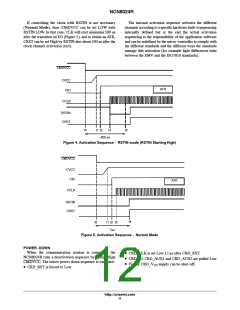
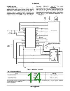
If controlling the clock with RSTIN is not necessary
The internal activation sequence activates the different
channels according to a specific hardware built−it sequencing
internally defined but at the end the actual activation
sequencing is the responsibility of the application software
and can be redefined by the micro−controller to comply with
the different standards and the different ways the standards
manage this activation (for example light differences exist
between the EMV and the ISO7816 standards).
(Normal Mode), then /CMDVCC can be set LOW with
RSTIN LOW. In that case, CLK will start minimum 500 ns
after the transition on I/O (Figure 5), and to obtain an ATR,
CRST can be set High by RSTIN also about 500 ns after the
clock channel activation (tact).
CMDVCC
CVCC
CIO
ATR
CCLK
RSTIN
CRST
t0
t1 t2
t4
t5
−200 ms
Figure 4. Activation Sequence − RSTIN mode (RSTIN Starting High)
CMDVCC
CVCC
CIO
ATR
CCLK
RSTIN
CRST
t4
t0
t1 t2 t3
t
act
Figure 5. Activation Sequence − Normal Mode
POWER−DOWN
When the communication session is completed the
NCN8024R runs a deactivation sequence by setting High
CMDVCC. The below power down sequence is executed:
• CRD_RST is forced to Low
• CRD_CLK is set Low 12 ms after CRD_RST.
• CRD_IO, CRD_AUX1 and CRD_AUX2 are pulled Low
• Finally CRD_V supply can be shut−off.
CC
http://onsemi.com
11

 ONSEMI [ ONSEMI ]