MT9M021, MT9M031
POWER-ON RESET AND STANDBY TIMING
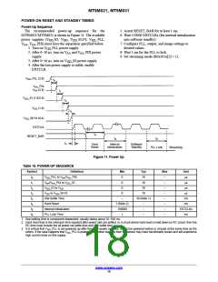
Power-Up Sequence
The recommended power-up sequence for the
MT9M021/MT9M031 is shown in Figure 11. The available
5. Assert RESET_BAR for at least 1 ms.
6. Wait 150000 EXTCLKs (for internal initialization
into software standby).
power supplies (V _IO, V , V _SLVS, V _PLL,
DD
DD
DD
DD
V
, V _PIX) must have the separation specified below.
7. Configure PLL, output, and image settings to
desired values.
AA AA
1. Turn on V _PLL power supply.
DD
2. After 0−10 ms, turn on V and V _PIX power
8. Wait 1 ms for the PLL to lock.
9. Set streaming mode (R0x301a[2] = 1).
AA
AA
supply.
3. After 0−10 ms, turn on V _IO power supply.
DD
4. After the last power supply is stable, enable
EXTCLK.
V
DD
_PLL (2.8)
t
0
V
V
AA
_PIX
(2.8)
AA
t
1
V
DD
_IO (1.8/2.8)
t
2
V
DD
(1.8)
t
3
V
DD
_SLVS (0.4)
EXTCLK
t
4
RESET_BAR
t
5
t
6
t
X
Hard
Reset
Internal
Initialization
Software
Standby
PLL Lock
Streaming
Figure 11. Power Up
Table 18. POWER-UP SEQUENCE
Symbol
Definition
_PLL to V /V _PIX
Min
0
Typ
Max
Unit
ms
t
t
t
t
V
10
–
–
–
–
–
–
–
–
0
1
2
3
X
DD
AA AA
V
V
V
/V _PIX to V _IO
0
10
ms
AA AA
DD
_IO to V
0
10
ms
DD
DD
DD
to V _SLVS
0
10
ms
DD
t
Xtal Settle Time
Hard Reset
–
30 (Note 1)
ms
ms
t
4
t
5
t
6
1 (Note 2)
–
–
–
Internal Initialization
PLL Lock Time
150000
1
EXTCLKs
ms
1. Xtal settling time is component-dependent, usually taking about 10–100 ms.
2. Hard reset time is the minimum time required after power rails are settled. In a circuit where hard reset is held down by RC circuit, then the
RC time must include the all power rail settle time and Xtal settle time.
3. It is critical that V _PLL is not powered up after the other power supplies. It must be powered before or at least at the same time as the
DD
others. If the case happens that V _PLL is powered after other supplies then the sensor may have functionality issues and will experience
DD
high current draw on this supply.
www.onsemi.com
18

 ONSEMI [ ONSEMI ]