MT9M021, MT9M031
Power-Down Sequence
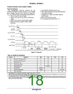
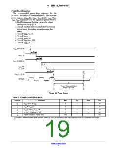
The recommended power-down sequence for the
MT9M021/MT9M031 is shown in Figure 12. The available
power supplies (V _IO, V , V _SLVS, V _PLL,
DD
DD
DD
DD
V
, V _PIX) must have the separation specified below.
AA AA
1. Disable streaming if output is active by setting
standby R0x301a[2] = 0.
2. The soft standby state is reached after the current
row or frame, depending on configuration, has
ended.
3. Turn off V _SLVS.
DD
4. Turn off V
.
DD
5. Turn off V _IO.
DD
6. Turn off V /V _PIX.
AA AA
7. Turn off V _PLL.
DD
V
DD
_SLVS (0.4)
t
0
V
DD
(1.8)
t
1
V
DD
_IO (1.8/2.8)
t
2
V
V
AA
_PIX
(2.8)
AA
t
3
V
DD
_PLL (2.8)
EXTCLK
t
4
Power Down until Next
Power Up Cycle
Figure 12. Power Down
Table 19. POWER-DOWN SEQUENCE
Symbol
Parameter
Min
0
Typ
–
Max
Unit
ms
t
0
t
1
t
2
t
3
t
4
V
V
V
_SLVS to V
DD
–
–
–
–
–
DD
DD
DD
to V _IO
0
–
ms
DD
_IO to V /V _PIX
0
–
ms
AA AA
V
/V _PIX to V _PLL
0
–
ms
AA AA
DD
PwrDn until Next PwrUp Time
100
–
ms
1. t is required between power down and next power up time; all decoupling caps from regulators must be completely discharged.
4
www.onsemi.com
19

 ONSEMI [ ONSEMI ]