MC54/74HC390
APPLICATIONS INFORMATION
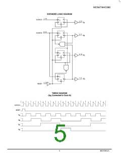
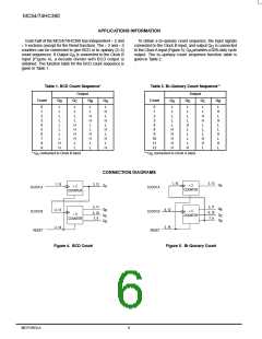
Each half of the MC54/74HC390 has independent ÷ 2 and
÷ 5 sections (except for the Reset function). The ÷ 2 and ÷ 5
counters can be connected to give BCD or bi–quinary (2–5)
To obtain a bi–quinary count sequence, the input signals
connected to the Clock B input, and output Q is connected
D
to the Clock A input (Figure 5). Q provides a 50% duty cycle
A
count sequences. If Output Q is connected to the Clock B
output. The bi–quinary count sequence function table is
given in Table 2.
A
input (Figure 4), a decade divider with BCD output is
obtained. The function table for the BCD count sequence is
given in Table 1.
Table 1. BCD Count Sequence*
Output
Table 2. Bi–Quinary Count Sequence**
Output
Count
Count
Q
Q
Q
Q
Q
Q
Q
Q
B
D
C
B
A
A
D
C
0
1
2
3
4
5
6
7
8
9
L
L
L
L
L
L
H
L
H
L
H
L
H
L
H
0
1
2
3
4
8
9
10
11
12
L
L
L
L
L
H
H
H
H
H
L
L
L
H
L
H
L
L
H
L
H
L
L
L
L
L
L
L
L
H
H
L
H
H
L
L
L
L
H
L
L
L
L
H
L
H
H
L
L
L
H
H
L
L
H
H
H
H
L
L
H
H
L
L
L
* Q connected to Clock B input.
A
**Q connected to Clock A input.
D
CONNECTION DIAGRAMS
1, 15
3, 13
1, 15
3, 13
5, 11
Q
Q
÷ 2
COUNTER
A
÷
2
A
CLOCK A
CLOCK A
COUNTER
5, 11
6, 10
7, 9
Q
Q
4, 12
2, 14
B
4, 12
2, 14
B
÷
5
CLOCK B
RESET
CLOCK B
RESET
6, 10
7, 9
÷
5
Q
Q
COUNTER
Q
Q
C
D
C
D
COUNTER
Figure 4. BCD Count
Figure 5. Bi-Quinary Count
MOTOROLA
6
High–Speed CMOS Logic Data
DL129 — Rev 6

 ONSEMI [ ONSEMI ]