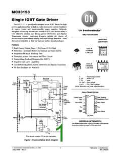
MC33153
ELECTRICAL CHARACTERISTICS (continued) (V = 15 V, V = 0 V, Kelvin GND connected to V . For typical values T = 25°C,
CC
EE
EE
A
for min/max values T is the operating ambient temperature range that applies (Note 3), unless otherwise noted.)
A
Characteristic
Symbol
Min
Typ
Max
Unit
UVLO
Startup Voltage
V
11.3
10.4
12
11
12.6
11.7
V
V
CC start
Disable Voltage
V
CC dis
COMPARATORS
Overcurrent Threshold Voltage (V
> 7.0 V)
> 7.0 V)
V
50
100
6.0
−
65
130
6.5
80
mV
mV
V
Pin8
SOC
Short Circuit Threshold Voltage (V
V
160
7.0
Pin8
SSC
Fault Blanking/Desaturation Threshold (V
> 100 mV)
V
th(FLT)
Pin1
Current Sense Input Current (V = 0 V)
I
−1.4
−10
mA
SI
SI
FAULT BLANKING/DESATURATION INPUT
Current Source (V = 0 V, V = 0 V)
I
chg
−200
1.0
−270
2.5
−300
−
mA
Pin8
Pin4
Discharge Current (V
= 15 V, V
= 5.0 V)
I
dschg
mA
Pin8
Pin4
TOTAL DEVICE
Power Supply Current
Standby (V = V , Output Open)
I
mA
CC
−
−
7.2
7.9
14
20
Pin 4
CC
Operating (C = 1.0 nF, f = 20 kHz)
L
3. Low duty cycle pulse techniques are used during test to maintain the junction temperature as close to ambient as possible.
= −40°C for MC33153 = +105°C for MC33153
T
T
high
low
ORDERING INFORMATION
Device
†
Operating Temperature Range
Package
Shipping
MC33153D
SOIC−8
98 Units / Rail
98 Units / Rail
MC33153DG
SOIC−8
(Pb−Free)
MC33153DR2
SOIC−8
1000 / Tape & Reel
1000 / Tape & Reel
T = −40° to +105°C
A
MC33153DR2G
SOIC−8
(Pb−Free)
MC33153P
PDIP−8
50 Units / Rail
50 Units / Rail
MC33153PG
PDIP−8
(Pb−Free)
†For information on tape and reel specifications, including part orientation and tape sizes, please refer to our Tape and Reel Packaging
Specifications Brochure, BRD8011/D.
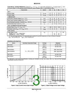
1.5
1.0
0.5
0
16
14
V
= 15 V
CC
T = 25°C
A
12
10
8.0
6.0
4.0
V
= 15 V
CC
2.0
0
T = 25°C
A
5.0
0
2.0
4.0
6.0
8.0
10
12
14
16
0
1.0
2.0
3.0
4.0
V , INPUT VOLTAGE (V)
in
V , INPUT VOLTAGE (V)
in
Figure 3. Output Voltage versus Input Voltage
Figure 2. Input Current versus Input Voltage
http://onsemi.com
3

 ONSEMI [ ONSEMI ]