MC33153
the IGBT is in the off−state, it will be subjected to changes
in voltage caused by the other devices. This is particularly
a problem when the opposite transistor turns on.
that the opto’s dv/dt capability is not exceeded. Like most
optoisolators, the HCPL4053 has an active low
open−collector output. Thus, when the LED is on, the output
will be low. The MC33153 has an inverting input pin to
interface directly with an optoisolator using a pullup
resistor. The input may also be interfaced directly to 5.0 V
CMOS logic or a microcontroller.
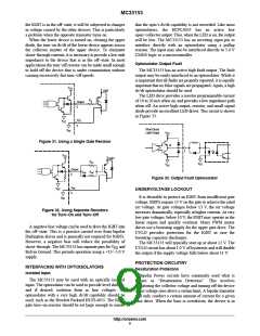
When the lower device is turned on, clearing the upper
diode, the turn−on dv/dt of the lower device appears across
the collector emitter of the upper device. To eliminate
shoot−through currents, it is necessary to provide a low sink
impedance to the device that is in the off−state. In most
applications the turn−off resistor can be made small enough
to hold off the device that is under commutation without
causing excessively fast turn−off speeds.
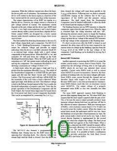
Optoisolator Output Fault
The MC33153 has an active high fault output. The fault
output may be easily interfaced to an optoisolator. While it
is important that all faults are properly reported, it is equally
important that no false signals are propagated. Again, a high
dv/dt optoisolator should be used.
V
CC
IGBT
The LED drive provides a resistor programmable current
of 10 to 20 mA when on, and provides a low impedance path
when off. An active high output, resistor, and small signal
diode provide an excellent LED driver. This circuit is shown
in Figure 33.
R
g
Output
5
V
EE
V
EE
3
Short Circuit
Latch Output
V
EE
V
CC
Figure 31. Using a Single Gate Resistor
Q
7
V
CC
IGBT
R
on
V
EE
V
EE
Output
D
off
R
off
5
Figure 33. Output Fault Optoisolator
V
EE
V
EE
UNDERVOLTAGE LOCKOUT
3
It is desirable to protect an IGBT from insufficient gate
voltage. IGBTs require 15 V on the gate to achieve the rated
on−voltage. At gate voltages below 13 V, the on−voltage
increases dramatically, especially at higher currents. At very
low gate voltages, below 10 V, the IGBT may operate in the
linear region and quickly overheat. Many PWM motor
drives use a bootstrap supply for the upper gate drive. The
UVLO provides protection for the IGBT in case the
bootstrap capacitor discharges.
V
EE
Figure 32. Using Separate Resistors
for Turn−On and Turn−Off
A negative bias voltage can be used to drive the IGBT into
the off−state. This is a practice carried over from bipolar
Darlington drives and is generally not required for IGBTs.
However, a negative bias will reduce the possibility of
shoot−through. The MC33153 has separate pins for V and
Kelvin Ground. This permits operation using a +15/−5.0 V
supply.
The MC33153 will typically start up at about 12 V. The
UVLO circuit has about 1.0 V of hysteresis and will disable
the output if the supply voltage falls below about 11 V.
EE
PROTECTION CIRCUITRY
Desaturation Protection
INTERFACING WITH OPTOISOLATORS
Isolated Input
Bipolar Power circuits have commonly used what is
known as “Desaturation Detection”. This involves
monitoring the collector voltage and turning off the device
if this voltage rises above a certain limit. A bipolar transistor
will only conduct a certain amount of current for a given
base drive. When the base is overdriven, the device is in
The MC33153 may be used with an optically isolated
input. The optoisolator can be used to provide level shifting,
and if desired, isolation from ac line voltages. An
optoisolator with a very high dv/dt capability should be
used, such as the Hewlett Packard HCPL4053. The IGBT
gate turn−on resistor should be set large enough to ensure
http://onsemi.com
9

 ONSEMI [ ONSEMI ]